背景


总结
Network Function Virtualization is a network architecture for virtualizing the entire class of network functions (NFs) on commodity off-the-shelf(现成的) general-purpose hardware.

参考资料:
]]>
Network Function Virtualization is a network architecture for virtualizing the entire class of network functions (NFs) on commodity off-the-shelf(现成的) general-purpose hardware.
参考资料:
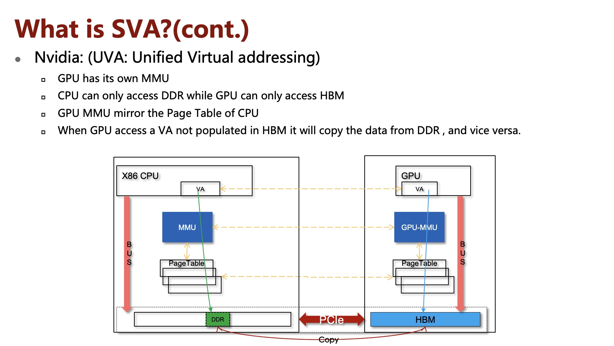
]]>On-Demand-Paging (ODP) is a technique to alleviate much of the shortcomings of memory registration. Applications no longer need to pin down the underlying physical pages of the address space, and track the validity of the mappings. Rather, the HCA requests the latest translations from the OS when pages are not present, and the OS invalidates translations which are no longer valid due to either non-present pages or mapping changes.
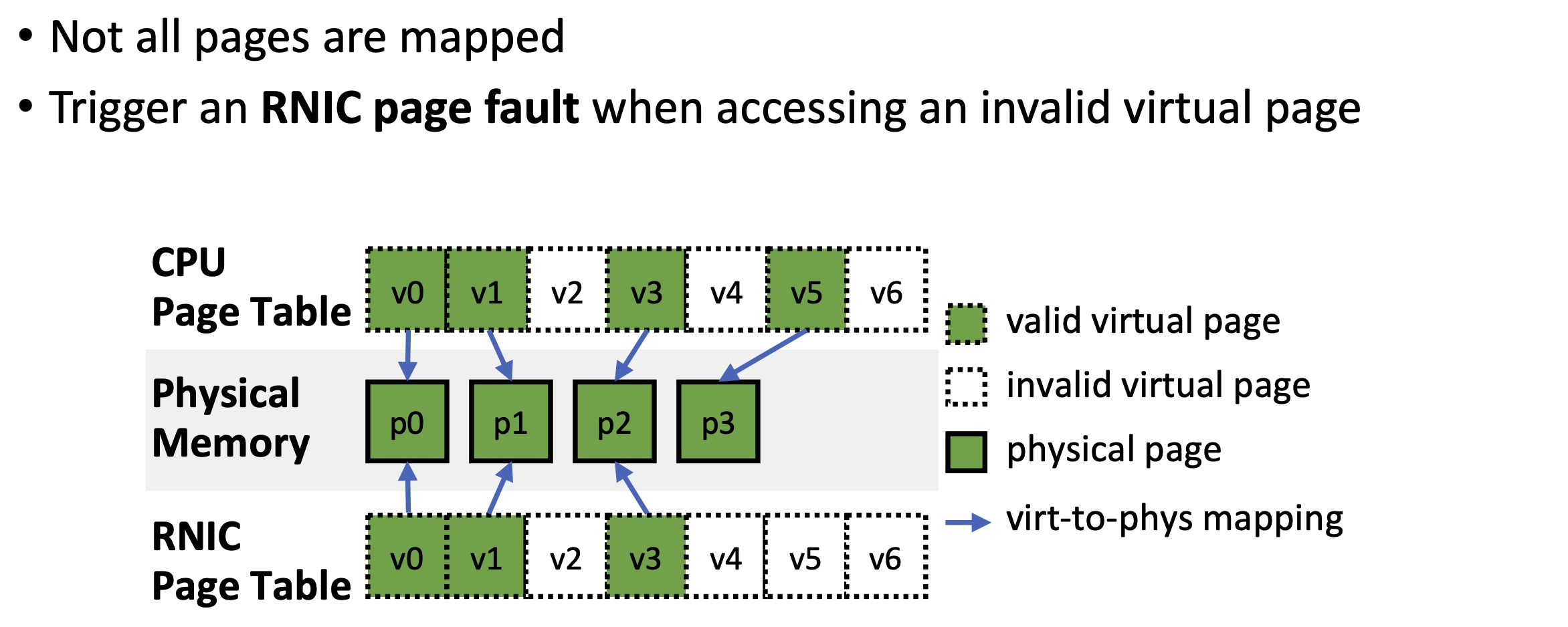
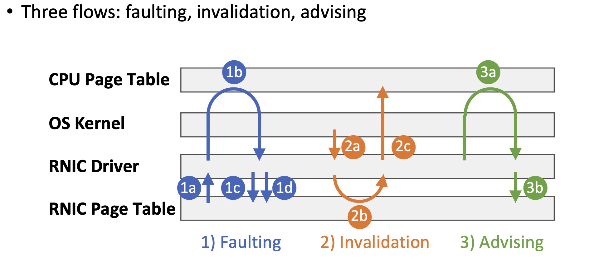
When an RDMA request accesses data on invalid virtual pages, (1a) the RNIC stalls the QP and raises an RNIC page fault interrupt. (1b) The driver requests the OS kernel for virtual-to-physical mappings via hmm_range_fault. The OS kernel triggers CPU page faults on these virtual pages and fills the CPU page table if necessary. (1c) The driver updates the mappings on the RNIC page table and (1d) resumes the QP.
When the OS kernel tries to unmap virtual pages in scenarios like swapping out or page migration, (2a)it notifies the RNIC driver to invalidate virtual pages via mmu_interval_notifier. (2b) The RNIC driver erases the virtual-to-physical mapping from the RNIC page table. (2c) The driver notifies the kernel that the physical pages are no longer used by the RNIC. Then, the OS kernel modifies the CPU page table and reuses the physical pages.
ODP MR(Memory Region) relies on faulting and invalidation flows to synchronize CPU and RNIC page tables.
An application can proactively request the RNIC driver to populate a range in the RNIC page table. The RNIC driver completes advising by steps (3a) – (3b), which are identical to steps (1b) – (1c).
1 | enum ib_odp_general_cap_bits { |
参考资料:
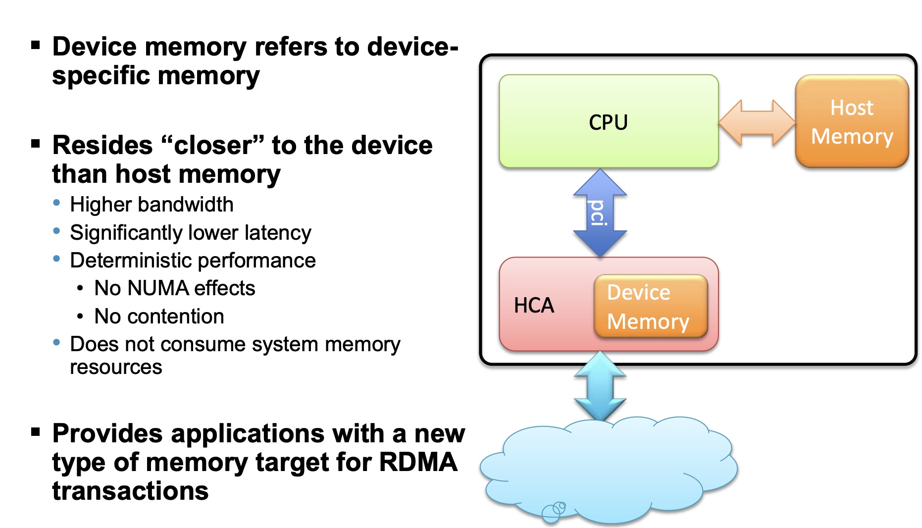
Device Memory is a verbs API that allows using on-chip memory, located on the device, as a data buffer for send/receive and RDMA operations. The device memory can be mapped and accessed directly by user and kernel applications, and can be allocated in various sizes, registered as memory regions with local and remote access keys for performing the send/ receive and RDMA operations. Using the device memory to store packets for transmission can significantly reduce transmission latency compared to the host memory.
staging buffer: 暂存缓冲区
可以类比于NVMe的CMB,RDMA Device Memory以mmio的形式expose给host,目的是让RDMA直接使用Device Memory,无需DMA到host的内存,减少了PCIe TLP的交互。
Sherman(SIGMOD’22) is the first RDMA-based system that leverages on-chip memory of commodity RDMA NICs.
参考资料:
]]>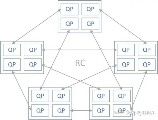
在没有SRQ的情况下,因为RC/UC/UD的接收方不知道对端什么时候会发送过来多少数据,所以必须做好最坏的打算,做好突发性收到大量数据的准备,也就是向RQ中下发足量的的接收WQE;另外RC服务类型可以利用流控机制来抑制发送方,也就是告诉对端”我这边RQ WQE不够了”,这样发送端就会暂时放缓或停止发送数据。
但是第一种方法由于是为最坏情况准备的,大部分时候有大量的RQ WQE处于空闲状态未被使用,这对内存是一种极大地浪费(主要是WQE指向的用于存放数据的内存空间);第二种方法虽然不用下发那么多RQ WQE了,但是流控是有代价的,即会增加通信时延。
而SRQ通过允许很多QP共享接收WQE(本身其实不是很大)以及用于存放数据的内存空间(这可是很大一块内存)来解决上面的问题。当任何一个QP收到消息后,硬件会从SRQ中取出一个WQE,根据其内容存放接收到的数据,然后硬件通过Completion Queue来返回接收任务的完成信息给对应的上层用户。
SRQ可以设置一个阈值,当队列中剩余的WQE数量小于阈值时,这个SRQ就会上报一个异步事件。提醒用户“队列中的WQE快用完了,请下发更多WQE以防没有地方接收新的数据”。这个阈值就被称为SRQ Limit,这个上报的事件就被称为SRQ Limit Reached。
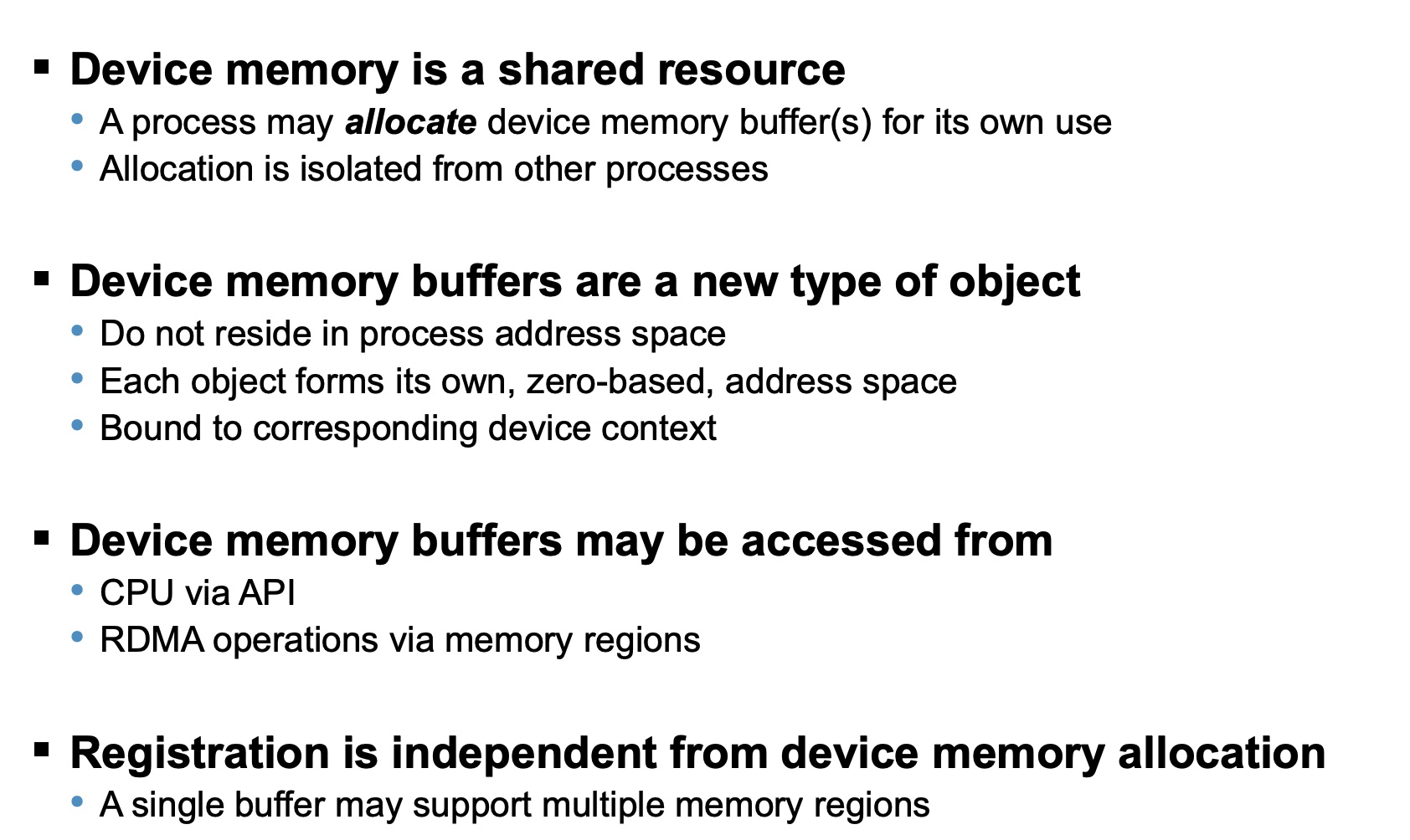
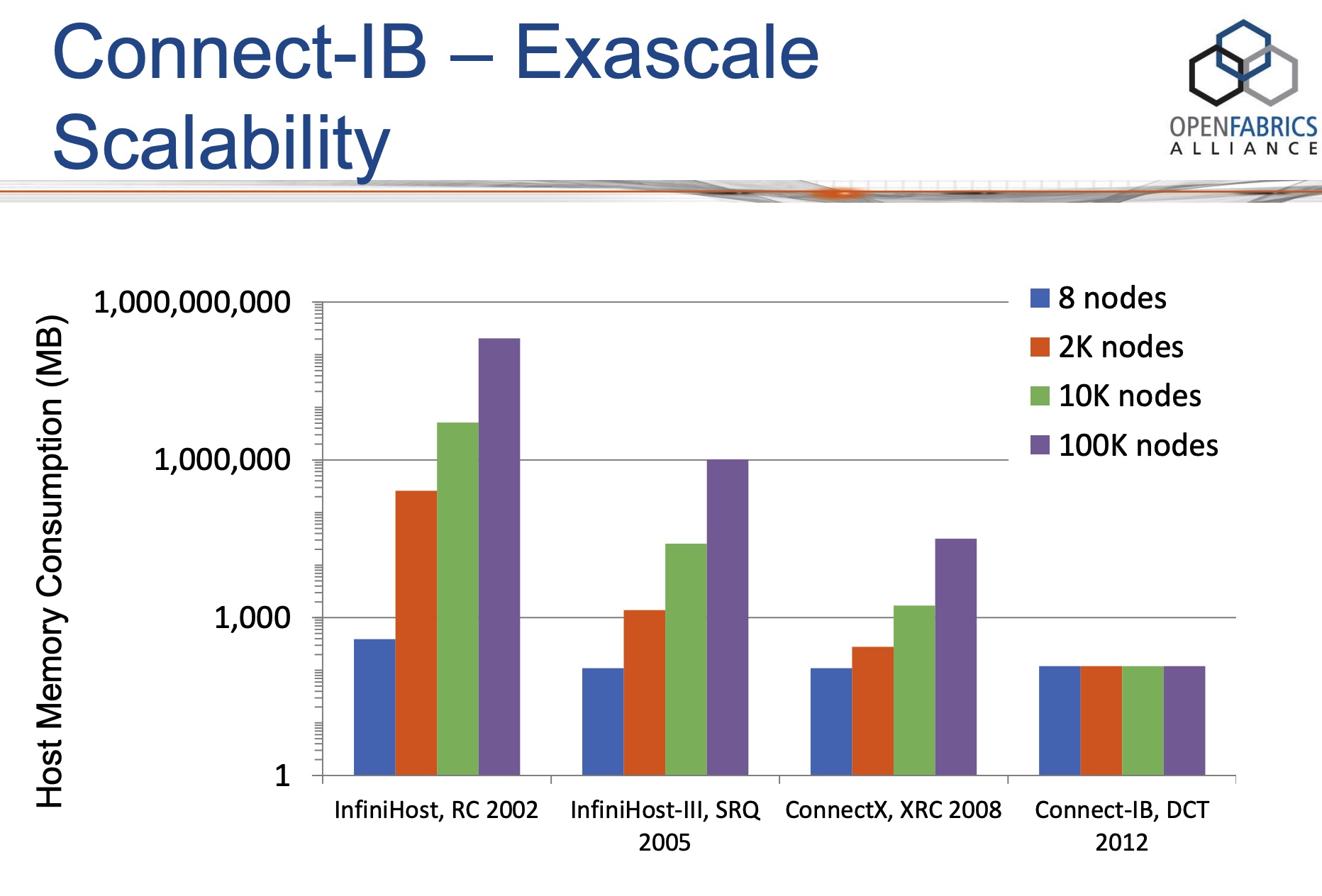
当前的计算节点一般都有多核,因此可以运行多进程。在这样的计算节点组成的集群中,如果想用RC连接建立full mesh的全连接拓扑时,每个节点就需要建立N*p*p个QP(这里假设集群有N个节点,每个节点上有p个进程,需要让任何2个进程都连通)。当集群扩张,N和p同时增长时,一个节点所需的RC QP资源将变得不可接受。
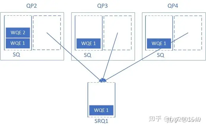
XRC的思想是当一个进程想与某个远程节点的p个进程通信时不需要跟各个进程建立p个连接而只需要跟对端节点建立一个连接,连接上传输的报文携带了对端目的进程号(XRC SRQ),报文到达连接对端(XRC TGT QP)时根据进程号分发至各个进程对应的XRC SRQ。这样源端进程只需要创建一个源端连接(XRC INI QP)就能跟对端所有进程通信了,这样所需总的QP数量就会除以p。
上图中XRC下标xyz的含义:x代表发起端的node号,y代表发起端的进程号,z代表接收端的node号。
XRC发起端QP,是XRC操作的源端队列,用于发出XRC操作,但它没有接收XRC操作的功能,对比常规RC QP来说可以认为它是只有SQ没有RQ。XRC操作在对端由XRC TGT QP处理。
XRC接收端QP,它处理XRC操作将其分发至报文SRQ number对应的SRQ。XRC TGT QP只能接收XRC操作,但它没有发出XRC操作的功能,对比常规RC QP来说可以认为它是只有RQ没有SQ。XRC操作在对端由XRC INI QP发出。
接收缓冲区(receive WQE)被放在XRC SRQ中以接收XRC请求,XRC请求中携带了XRC SRQ number,所以XRC TGT QP收到报文后会从报文指定的XRC SRQ中取receive WQE来存放XRC请求。
用于关联XRC TGT QP和XRC SRQ,XRC报文只能指定与XRC TGT QP在同一domain内的XRC SRQ,否则报文会被丢弃。这起到了隔离资源的作用,防止攻击报文随意指定XRC SRQ。
XRC INI QP和XRC TGT QP是一一对应的,host2上的每个进程在远端节点host0上都有自己对应的XRC TGT QP。XRC的共享体现在一个XRC TGT QP可以分发至多个XRC SRQ。一个进程一般只有一个XRC SRQ,它可以接收多个XRC TGT QP来的包。
Dynamically Connected transport (DCT) service is an extension to transport services to enable a higher degree of scalability while maintaining high performance for sparse traffic. Utilization of DCT reduces the total number of QPs required system wide by having Reliable type QPs dynamically connect and disconnect from any remote node. DCT connections only stay connected while they are active. This results in smaller memory footprint, less overhead to set connections and higher on-chip cache utilization and hence increased performance.
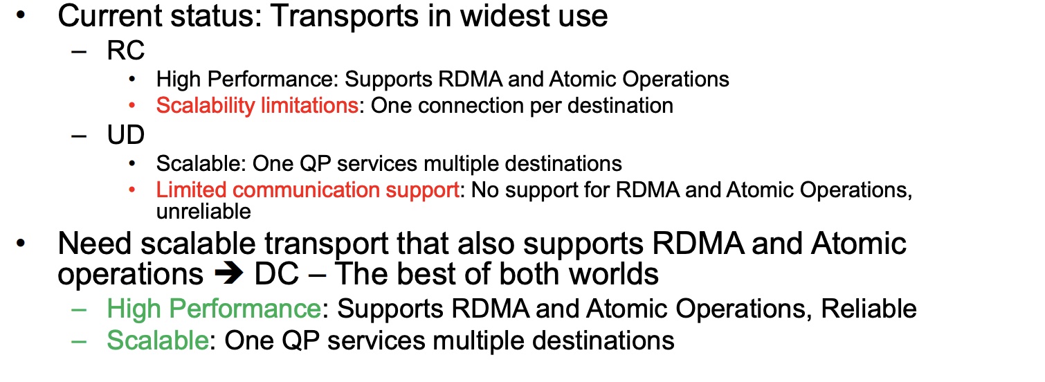
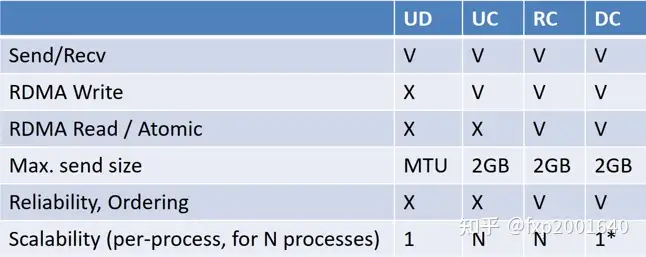
UD虽然扩展性很好,但是不支持read/write单边语义。RC虽然支持read/write单边语义,但是扩展性不好。DCT的初衷就是融合2者的优点,保持RC的read/write单边语义和可靠连接特性,同时像UD一样用一个QP去跟多个远端通信,保持良好的可扩展性。DCT一般用于sparse traffic场景。
想用RC连接建立full mesh的全连接拓扑时:
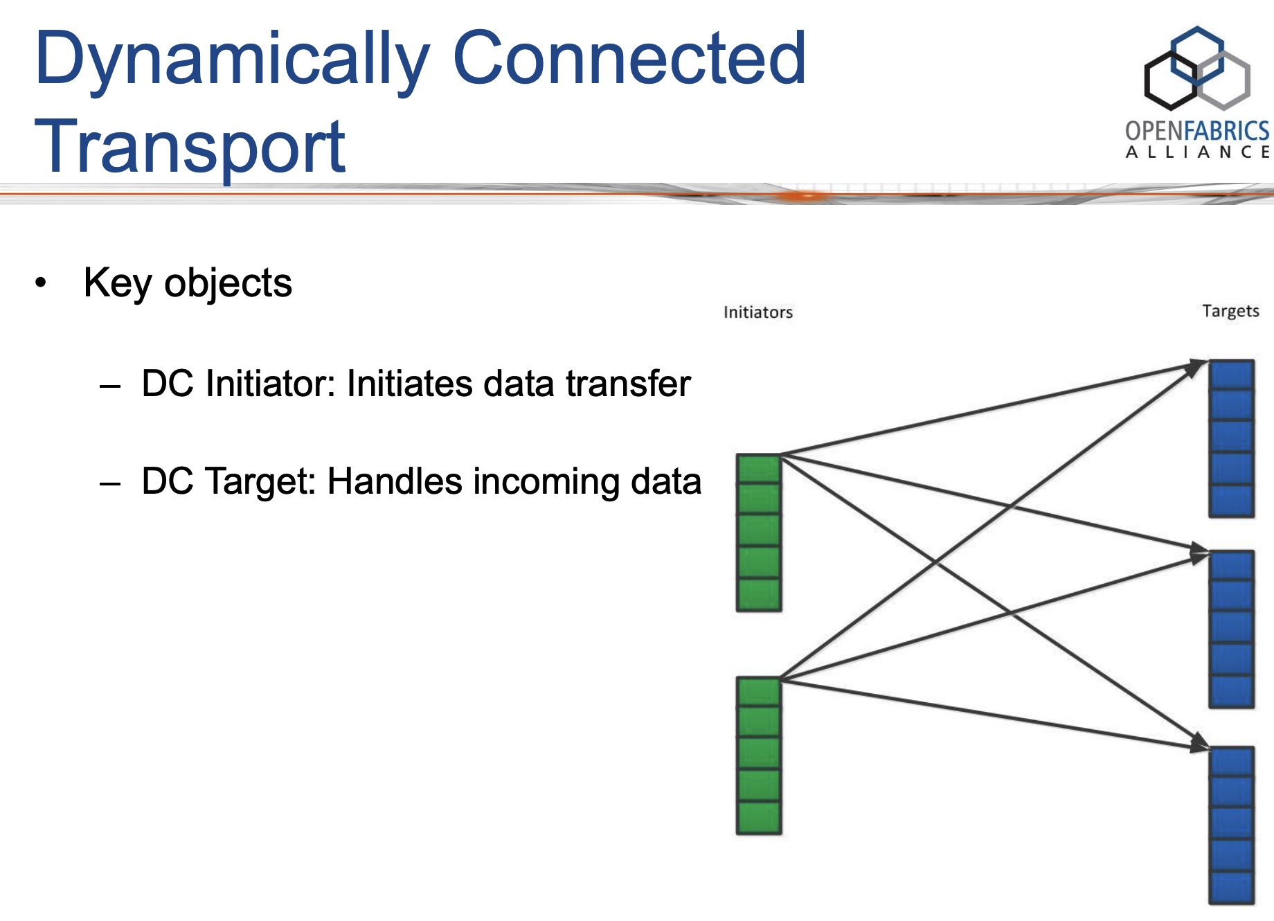
DCT具有非对称的API:DC在发送侧的部分称为DC initiator(DCI),在接收侧的部分称为DC target(DCT)。DCI和DCT不过是特殊类型的QP,它们依然遵循基本的QP操作,比如post send/receive。
DC意味着临时连接,在DCI上发送的每个send-WR都携带了目的地址信息,如果DCI当前连接的对端不是send-WR里携带的对端(node地址不一样),则它会首先断开当前的连接,再连接到send-WR里携带的对端。只要后续的send-WR里携带的都是当前已连接对端,则都可以复用当前已建立的连接。如果DCI在一段指定的时间内都没有发送操作则也会断开当前连接。注意DCT每次临时建立的是一个RC可靠连接。
DCT preserves their core connection-oriented design, but dynamically creates and destroys one-to-one connections. This provides software the illusion of using one QP to communicate with multiple remote machines, but at a prohibitively large performance cost for our workloads: DCT requires three additional network messages when the target machine of a DCT queue pair changes: a disconnect packet to the current machine, and a two-way handshake with the next machine to establish a connection[FaSST, OSDI’16].
所以DCT在sparse traffic场景中,性能才高。
KRCORE: a microsecond-scale RDMA control plane for elastic computing(ATC’22)
参考资料:
]]>1 | static void smp_call_function_many_cond(const struct cpumask *mask, |
csd_lock_wait会调用到pause命令1
2
3
4csd_lock_wait
└── smp_cond_load_relaxed
└── cpu_relax
└── asm volatile("rep; nop")
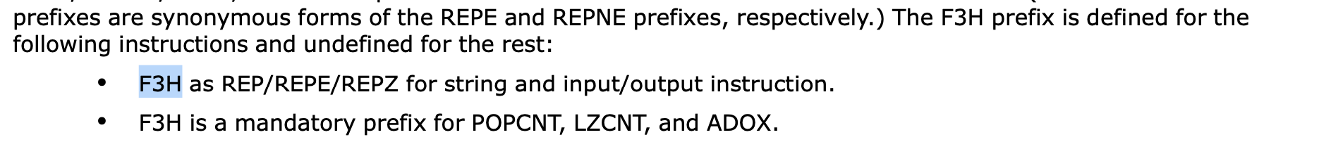
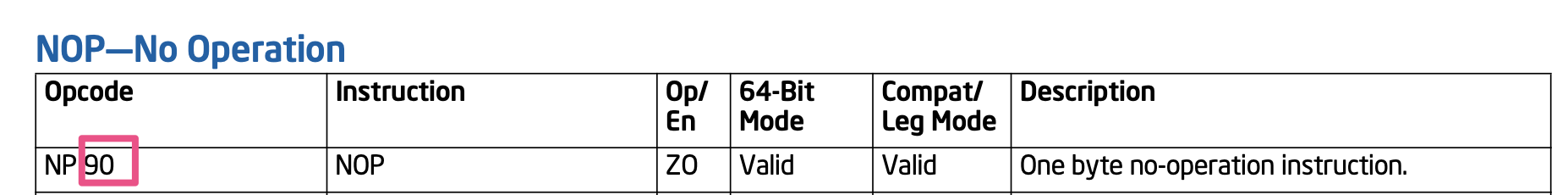
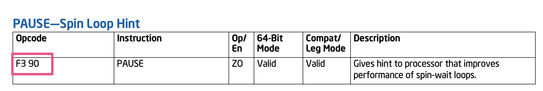
rep;nop的机器码是f3 90,其实就是pause指令的机器码,相当于pause的一个”别名”。
参考资料:
]]>User-Mode Memory Registration (UMR) supports the creation of memory keys for non-contiguous memory regions. This includes the concatenation(连接) of arbitrary contiguous regions of memory, as well as regions with regular structure.
Three examples of non-contiguous regions of memory that are used to form new contiguous regions of memory are described below.

如上图所示,我们之前创建了3个常规的MR:MR1(green), MR2(purple), MR3(red),现在我们想从这三个MR中各抽取一部分拼接起来形成一个新的连续的MR:第一块是MR1(v0-v1)部分,第二块是MR2(v2-v3)部分,第三块是MR3(v4-v5)部分。这个新的MR有一个新的base VA地址,长度是3个小块的长度之和。这样虽然内部是不连续的,但在外部访问者看来这个MR是连续的。

如上图所示,当我们做一个矩阵的转置时,需要把一列的元素拼成新的行,这个行就成了新的连续的MR。

如上图所示,2个老矩阵的列相互交织形成新的列,这是一个新的VA连续的MR,它有自己新的base address和length。
UMR会创建新的memory keys、VA(Virtual Address)地址和MTT entries;在MTT entry中,保证新的VA地址指向目标PA(Physical Address)即可。
参考资料:
]]>
通常,寄主操作系统的内核部分运行在EL1,控制虚拟化的部分运行在EL2。然而,这种设计有一个明显的问题。VHE之前的Hypervisor通常需要设计成high-visor和low-visor两部分,前者运行在EL1,后者运行在EL2。分层设计在系统运行时会造成很多不必要的上下文切换,带来不少设计上的复杂性和性能开销。为了解决这个问题,虚拟化主机扩展 (Virtualization Host Extensions, VHE)应运而生。该特性由Armv8.1-A引入,可以让寄主操作系统的内核部分直接运行在EL2上。


参考资料:
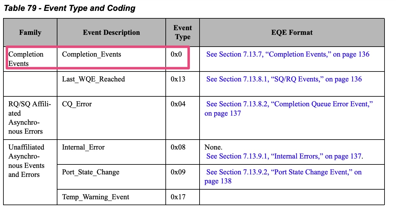
]]>HCA has multiple sources that can generate events (completion events, asynchronous events/
errors). Once an event is generated internally, it can be reported to the host software via the Event
Queue mechanism. The EQ is a memory-resident circular buffer used by hardware to write event
cause information for consumption by the host software. Once event reporting is enabled, event
cause information is written by hardware to the EQ when the event occurs. If EQ is armed, HW
will subsequently generate an interrupt on the device interface (send MSI-X message or assert
the pin) as configured in the EQ.
Q1: 都有cq了,为什么还要有completion EQ?
A1: 如果只有cq,就只能用轮询方式了,加上ceq之后,中断上来就能从ceqe中拿到哪个cq有数据
Q2: 为什么不能为每个cq分配一个中断vector,这样就无需eq机制了?
A2: 一个RDMA设备的CQ会很多,大概率会超过2048个,此时就超过了MSI-x table的上限,因而引入了eq机制,将多个cq绑定到1个eq上,然后为每个eq分配一个中断vector,控制eq的数量,就会保证vector个数不超过MSI-x table的上限
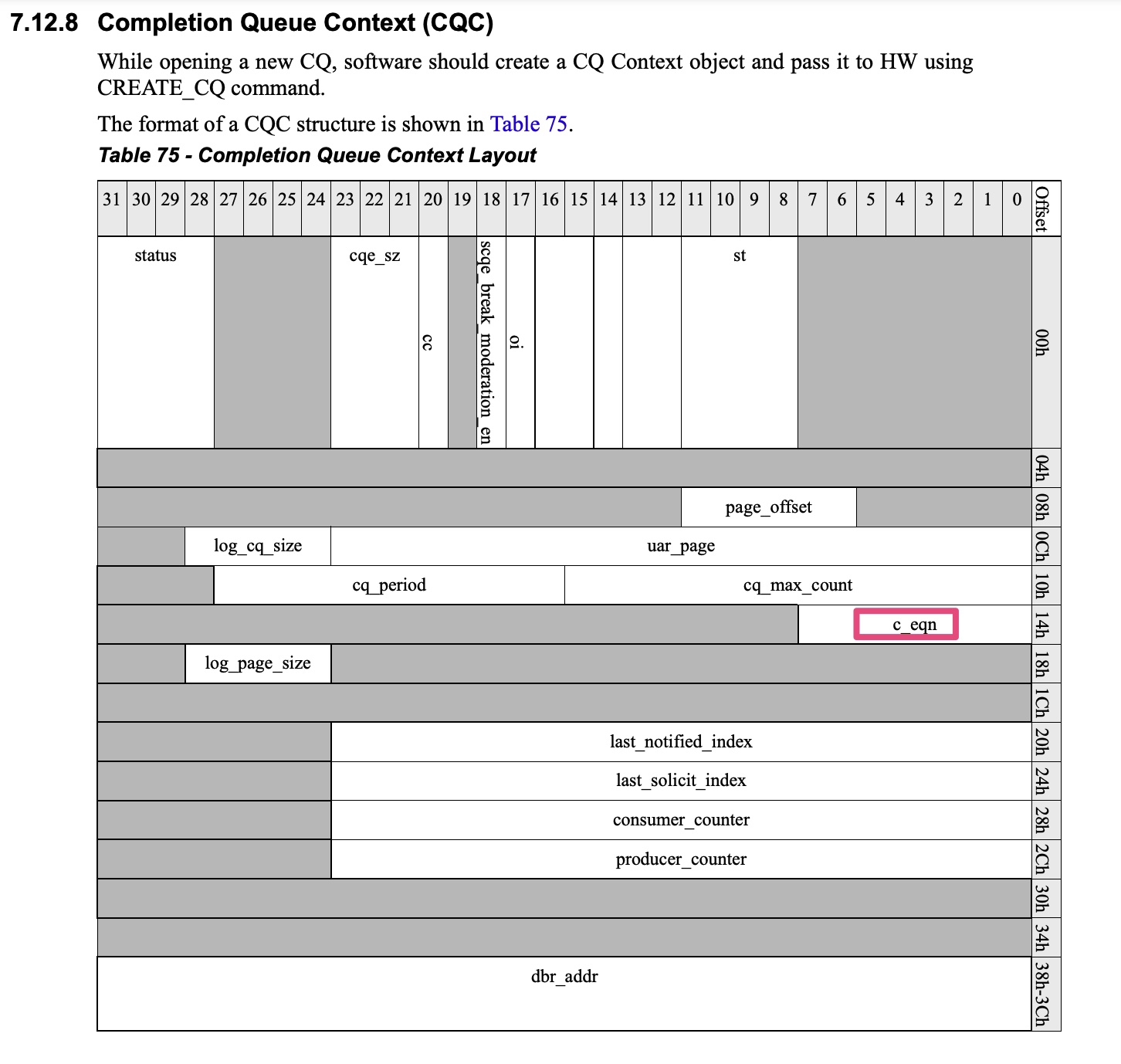
Q3: CQ与EQ是如何绑定的?
A3: While creating a CQ, software configures the EQ number to which this CQ will report completion events.
Event queue (EQ) is the main notification way from erdma hardware to its driver. Each erdma device contains 2 kinds EQs: asynchronous EQ (AEQ) and completion EQ (CEQ). Per device has 1 AEQ, which used for RDMA async event report, and max to 32 CEQs (numbered for CEQ0 to CEQ31). CEQ0 is used for cmdq completion event report, and the rest CEQs are used for RDMA completion event report.
1 | static int create_cq_cmd(struct erdma_ucontext *uctx, struct erdma_cq *cq) |
1 | int erdma_create_cq(struct ib_cq *ibcq, const struct ib_cq_init_attr *attr, |
1 | static irqreturn_t erdma_intr_ceq_handler(int irq, void *data) |
1 | erdma_intr_ceq_task |

1 | mlx4_ib_create_cq[mlx4_ib_dev_ops.create_cq] |
1 | int mlx4_cq_alloc(struct mlx4_dev *dev, int nent, |
1 | enum mlx4_event { |
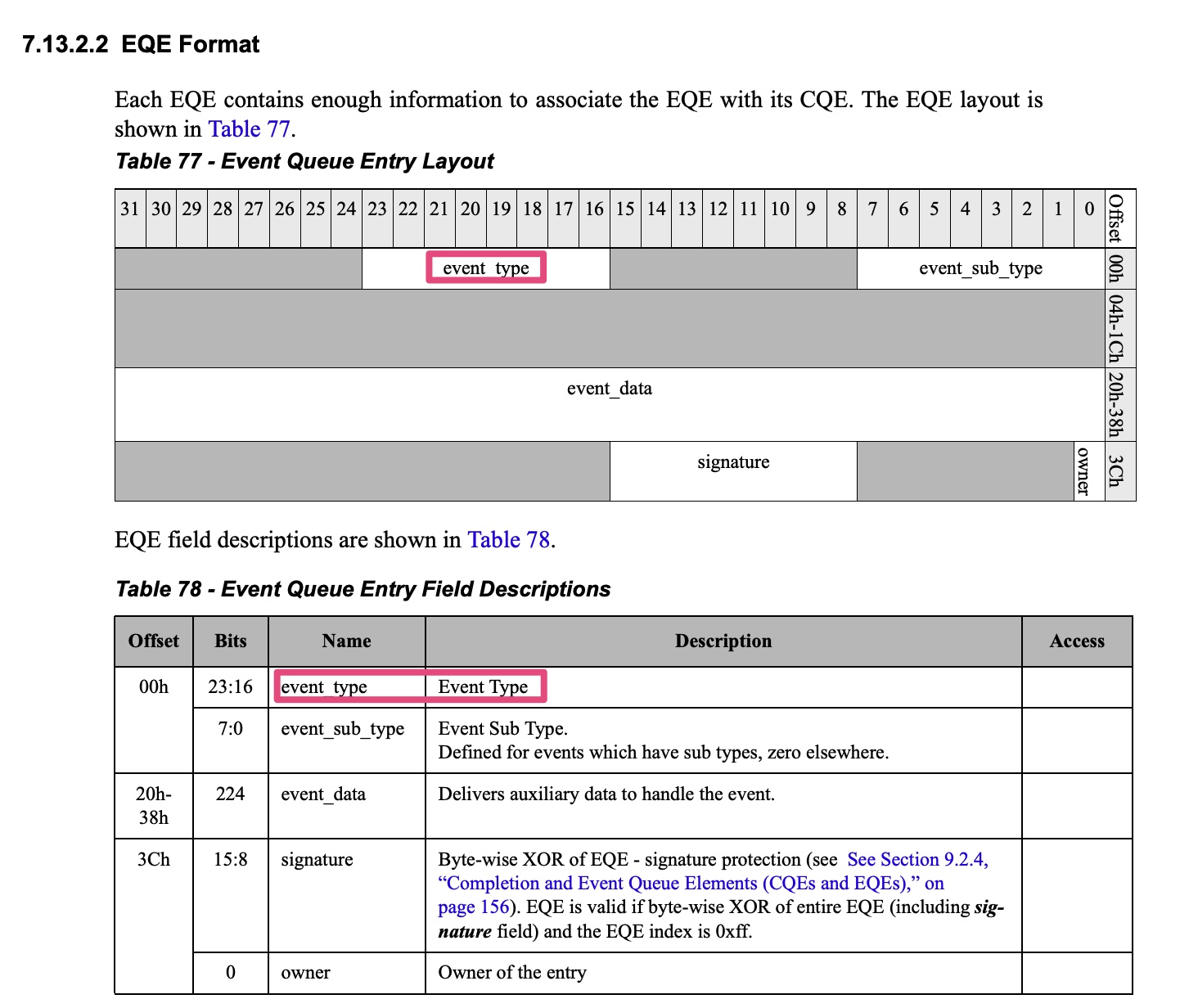
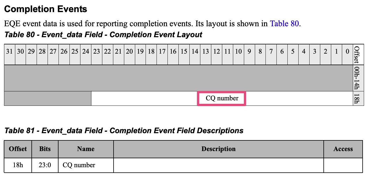
cqn = be32_to_cpu(eqe->event.comp.cqn) & 0xffffff保证了cq number就是event data的0~23位。
参考资料:
]]>The HCA command interface is used for:
The HCA is configured using the command queues. Each function has its own command queues to get commands from its HCA driver.
The command queue is the transport that is used to pass commands to the HCA.
cmdq其实属于一种sq(Send Queue),可以类比于NVMe的admin sq(submission queue)。
对于不同类型的RDMA设备,cmdq的具体实现是存在差异的。
mellanox mlx4 cmdq的细节,可以参考spec中的7.14 Command Interface一节。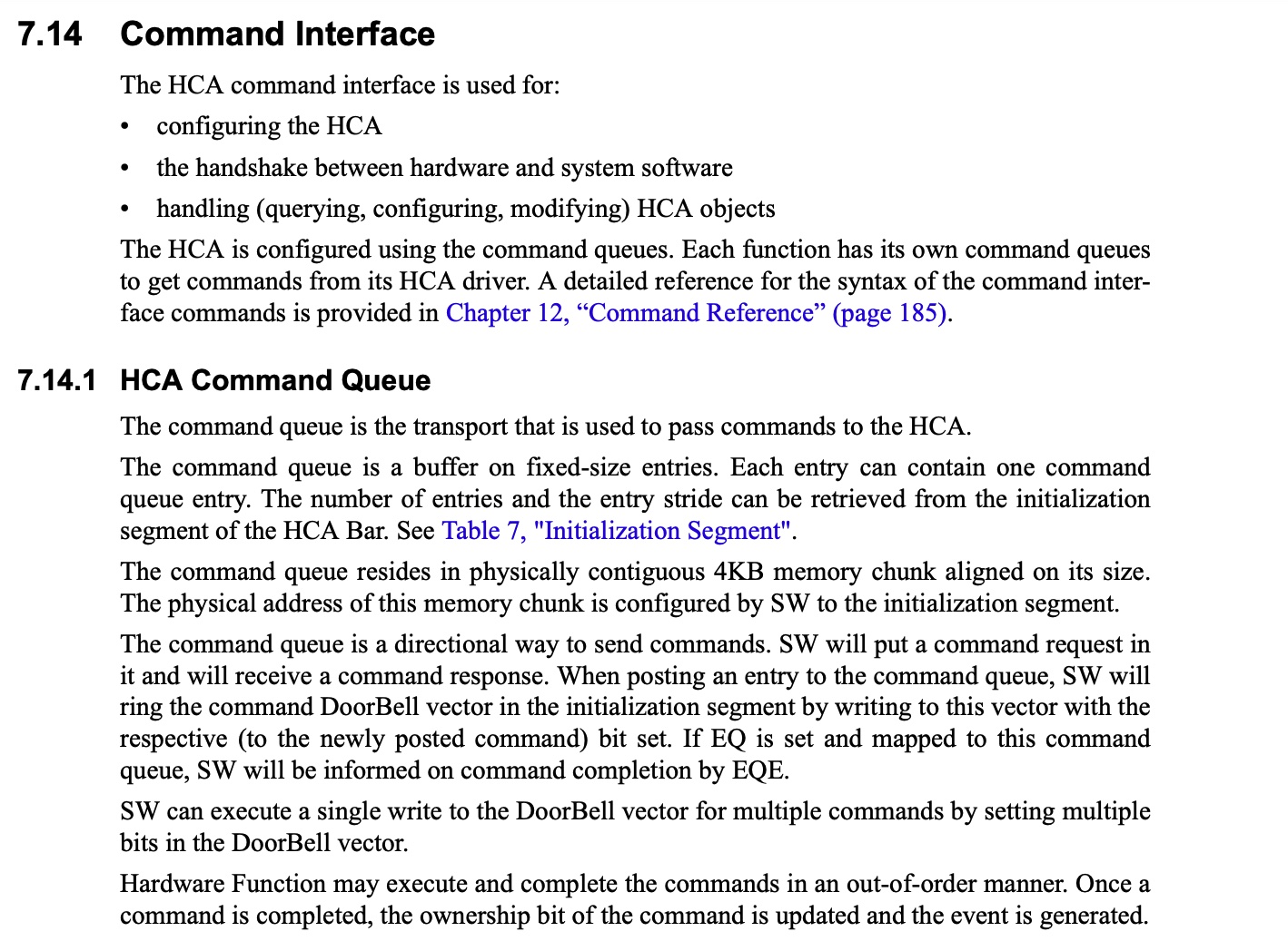
Cmdq is the main control plane channel between erdma driver and hardware. After erdma device is initialized, the cmdq channel will be active in the whole lifecycle of this driver.
eRDMA支持如下命令:1
2
3
4
5
6
7
8
9
10
11
12
13
14
15
16
17
18
19
20
21enum CMDQ_RDMA_OPCODE {
CMDQ_OPCODE_QUERY_DEVICE = 0,
CMDQ_OPCODE_CREATE_QP = 1,
CMDQ_OPCODE_DESTROY_QP = 2,
CMDQ_OPCODE_MODIFY_QP = 3,
CMDQ_OPCODE_CREATE_CQ = 4,
CMDQ_OPCODE_DESTROY_CQ = 5,
CMDQ_OPCODE_REFLUSH = 6,
CMDQ_OPCODE_REG_MR = 8,
CMDQ_OPCODE_DEREG_MR = 9
};
enum CMDQ_COMMON_OPCODE {
CMDQ_OPCODE_CREATE_EQ = 0,
CMDQ_OPCODE_DESTROY_EQ = 1,
CMDQ_OPCODE_QUERY_FW_INFO = 2,
CMDQ_OPCODE_CONF_MTU = 3,
CMDQ_OPCODE_CONF_DEVICE = 5,
CMDQ_OPCODE_ALLOC_DB = 8,
CMDQ_OPCODE_FREE_DB = 9,
};
1 | static const struct ib_device_ops erdma_device_ops = { |
struct ib_device_ops - InfiniBand device operations, 其实是内核与cmdq的交互接口。以alloc_mr为例,用户态下发创建Memory Region的请求到内核,此时erdma_ib_alloc_mr就会被调用。1
2
3
4erdma_ib_alloc_mr
└── regmr_cmd
├── erdma_cmdq_build_reqhdr(&req.hdr, CMDQ_SUBMOD_RDMA, CMDQ_OPCODE_REG_MR)
└── erdma_post_cmd_wait
最终,eRDMA driver会往cmdq中下发CMDQ_OPCODE_REG_MR命令来创建Memory Region。
1 | erdma_post_cmd_wait |
1 | erdma_probe |
Q: cmdq已经有cq了,为什么还需要eq(CEQ0)?
A: 如果只有cq,就只能用轮询模式了,加上ceq之后,cmdq与eq配合就能完成中断通知。
1 | static irqreturn_t erdma_comm_irq_handler(int irq, void *data) |
1 | erdma_cmdq_completion_handler |
1 | ... |
参考资料:
]]>UDP Segmentation Offload (USO)is a feature that enables network interface cards (NICs) to offload the segmentation of UDP datagrams that are larger than the maximum transmission unit (MTU) of the network medium.
UDP fragmentation offload allows a device to fragment an oversized UDP datagram into multiple IPv4 fragments.
There is a USO feature that is different from existing UFO:
VIRTIO_NET_F_HOST_USO (56)
Device can receive USO packets. Unlike UFO (fragmenting the packet) the USO splits large UDP packet to several segments when each of these smaller packets has UDP header.
参考资料:
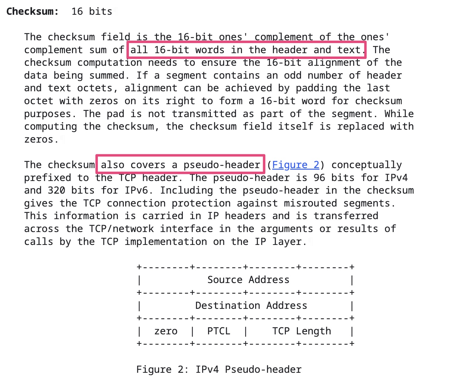
]]>很多网络协议,例如IP、TCP、UDP都有自己的校验和(checksum)。
TCP校验和计算三部分:TCP头部、TCP数据和TCP伪头部。TCP校验和是必须的。
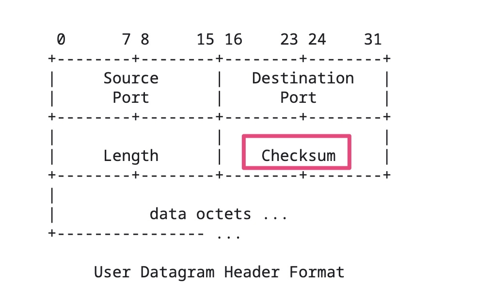
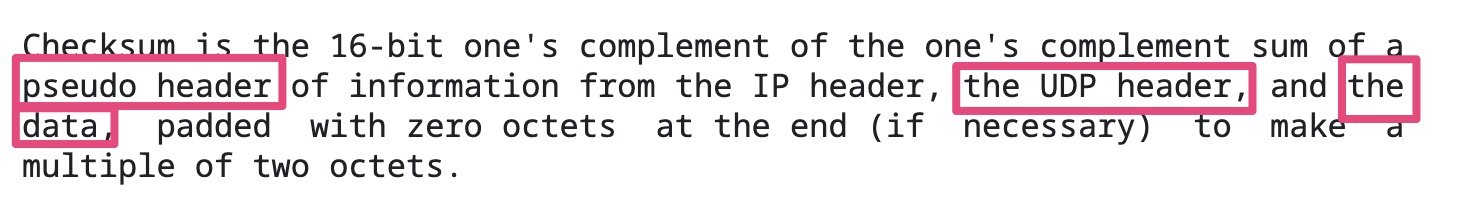
UDP校验和计算三部分:UDP头部、UDP数据和UDP伪头部。UDP校验和是可选的。
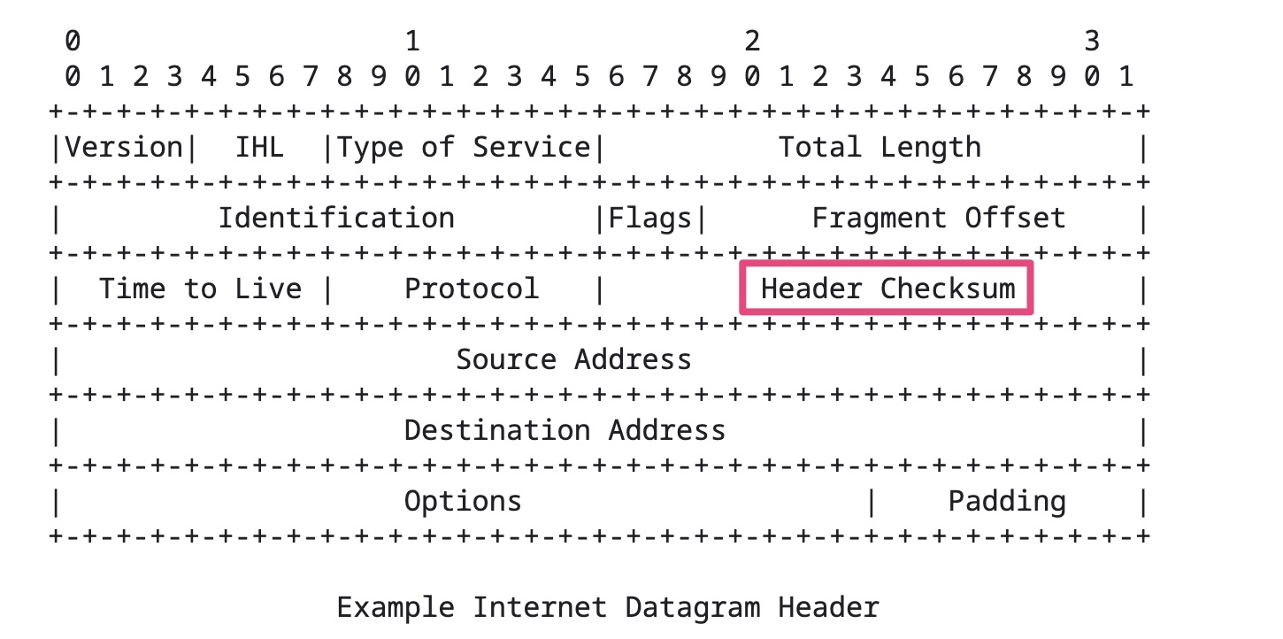
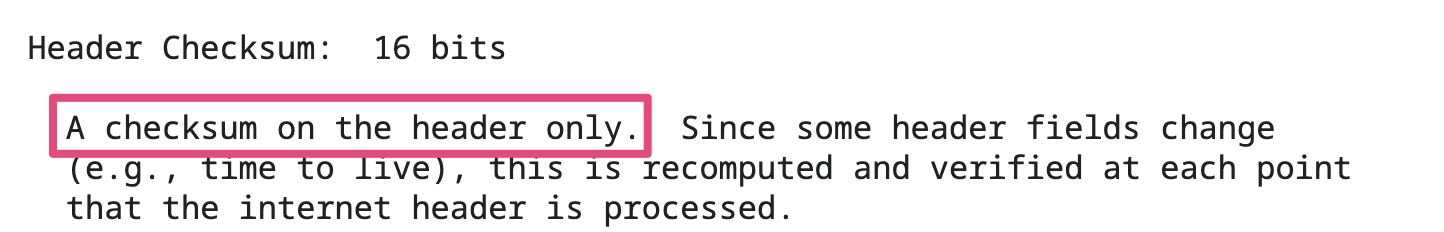
IP校验和只计算检验IP数据报的首部,但不包括IP数据报中的数据部分。
传统上,校验和的计算(发送数据包)和验证(接收数据包)是通过CPU完成的。这对CPU的影响很大,因为校验和需要每个字节的数据都参与计算。对于一个100G带宽的网络,需要CPU最多每秒计算大约12G的数据。
为了减轻这部分的影响,现在的网卡,都支持校验和的计算和验证。系统内核在封装网络数据包的时候,可以跳过校验和。网卡收到网络数据包之后,根据网络协议的规则,进行计算,再将校验和填入相应的位置。
因为Checksum offload的存在,在用tcpdump之类的抓包分析工具时,有时会发现抓到的包提示校验和错误(checksum incorrect)。tcpdump抓到的网络包就是系统内核发给网卡的网络包,如果校验和放到网卡去计算,那么tcpdump抓到包的时刻,校验和还没有被计算出来,自然看到的是错误的值。
VIRTIO_NET_F_CSUM (0)
Device handles packets with partial checksum. This “checksum offload” is a common feature on modern network cards.
VIRTIO_NET_F_HOST_TSO4
Requires VIRTIO_NET_F_CSUM.
由上述描述可知TSO需要Checksum offload的支持。因为在enable TSO时,TCP/IP协议栈并不知道最终的网络数据包是什么样,自然也没办法完成校验和计算。
参考资料:
]]>分段特指发生在使用TCP协议的传输层中的数据切分行为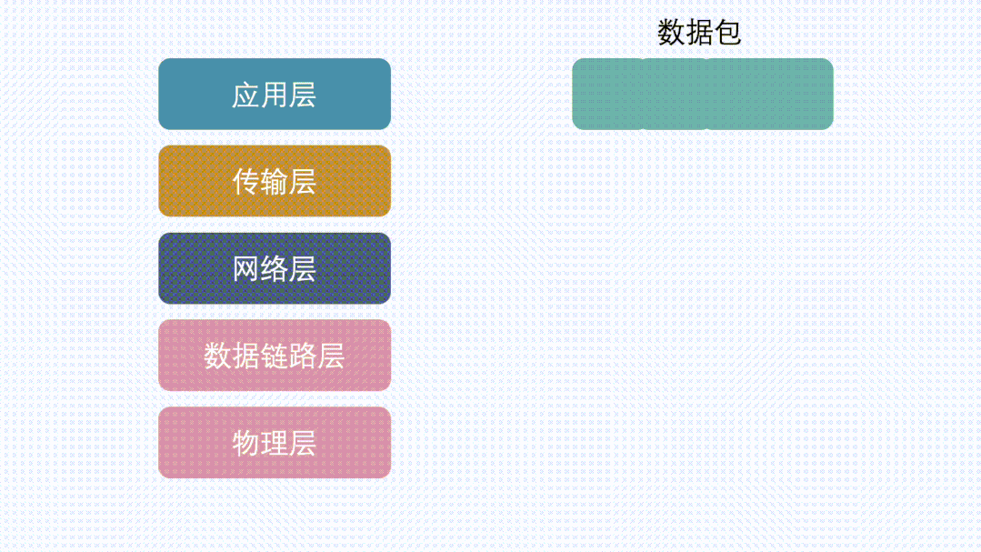
分片特指发生在使用IP协议的网络IP层中的数据切分行为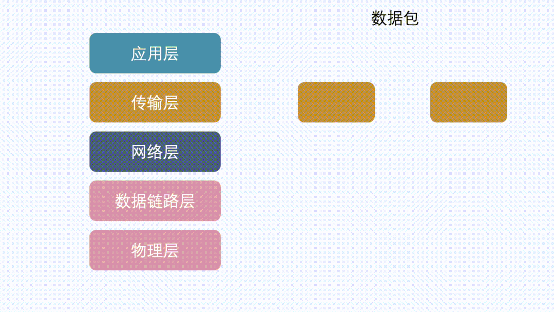
TCP协议在将用户数据传给IP层之前,会先将大段的数据根据MSS(Maximum Segment Size)分成多个小段,这个过程是Segmentation,分出来的数据是Segments。IP协议因为MTU(Maximum Transmission Unit)的限制,会将上层传过来的并且超过MTU的数据,分成多个分片,这个过程是Fragmentation,分出来的数据是Fragments。这两个过程都是大块的数据分成多个小块数据,区别就是一个在TCP(L4),一个在IP(L3)完成。
TCP 提交给 IP 层最大分段大小,不包含 TCP Header 和 TCP Option,只包含 TCP Payload ,MSS 是 TCP 用来限制应用层最大的发送字节数。
假设 MTU= 1500 byte,那么 MSS = 1500- 20(IP Header) -20 (TCP Header) = 1460 byte,如果应用层有 2000 byte 发送,那么需要两个切片才可以完成发送,第一个 TCP 切片 = 1460,第二个 TCP 切片 = 540。
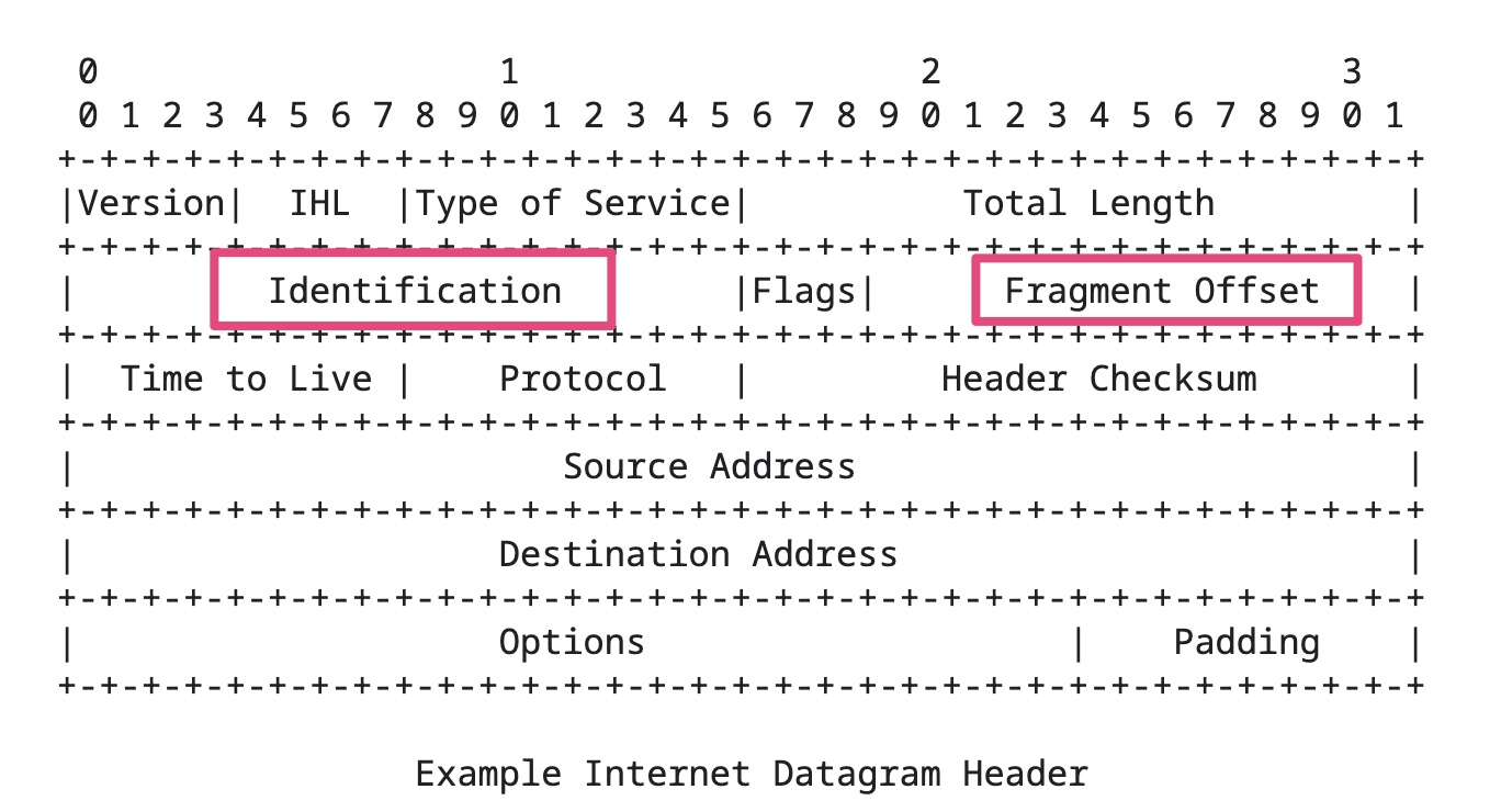
MTU是由数据链路层提供,为了告诉上层IP层,自己的传输能力是多大。IP层就会根据它进行数据包切分。一般 MTU=1500 Byte。
假设IP层有 <= 1500 byte 需要发送,只需要一个 IP 包就可以完成发送任务;假设 IP 层有 > 1500 byte 数据需要发送,需要分片才能完成发送,分片后的 IP Header ID 相同,同时为了分片后能在接收端把切片组装起来,还需要在分片后的IP包里加上各种信息。比如这个分片在原来的IP包里的偏移offset。
在一台机器的应用层到这台机器的网卡,这条链路上,基本上可以保证,MSS < MTU。

这其实是由传输效率决定的。虽然我们平时用的网络感觉挺稳定的,但其实这是因为TCP在背地里做了各种重传等保证了传输的可靠,其实背地里线路是动不动就丢包的,而越大的包,发生丢包的概率就越大。
那是不是包越小就越好?也不是
如果选择一个比较小的长度,假设选择MTU为300Byte,TCP payload = 300 - IP Header - TCP Header = 300 - 20 - 20 = 260 byte。那有效传输效率= 260 / 300 = 86%
而如果以太网MTU长度为1500,那有效传输效率= 1460 / 1500 = 96% ,显然比 86% 高多了。
所以,包越小越不容易丢包,包越大,传输效率又越高,因此权衡之下,选了1500。
由于本身IP层就会做分片这件事情。就算TCP不分段,到了IP层,数据包也会被分片,数据也能正常传输。
既然网络层就会分片了,那么TCP为什么还要分段?是不是有些多此一举?
假设有一份数据,较大,且在TCP层不分段,如果这份数据在发送的过程中出现丢包现象,TCP会发生重传,那么重传的就是这一大份数据(虽然IP层会把数据切分为MTU长度的N多个小包,但是TCP重传的单位却是那一大份数据)。
如果TCP把这份数据,分段为N个小于等于MSS长度的数据包,到了IP层后加上IP头和TCP头,还是小于MTU,那么IP层也不会再进行分片。此时在传输路上发生了丢包,那么TCP重传的时候也只是重传那一小部分的MSS段。效率会比TCP不分段时更高。
类似的,传输层除了TCP外,还有UDP协议,但UDP本身不会分段,所以当数据量较大时,只能交给IP层去分片,然后传到底层进行发送。
正常情况下,在一台机器的传输层到网络层这条链路上,如果传输层对数据做了分段,那么IP层就不会再分片。如果传输层没分段,那么IP层就可能会进行分片。
数据在TCP分段,就是为了在IP层不需要分片,同时发生重传的时候只重传分段后的小份数据。
在发送端,TCP分段后,IP层就不会再分片了。
但是整个传输链路中,可能还会有其他网络层设备,而这些设备的MTU可能小于发送端的MTU。此时虽然数据包在发送端已经分段过了,但是在IP层还会再分片一次。
如果链路上还有设备有更小的MTU,那么还会再分片,最后所有的分片都会在接收端进行组装。
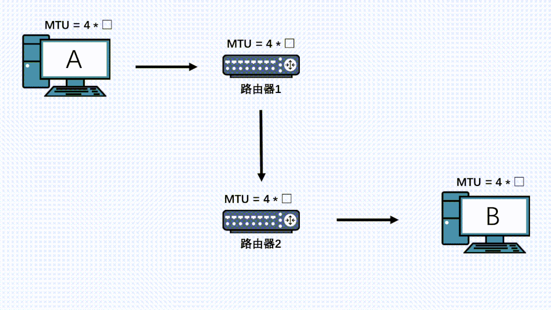
因此,就算TCP分段过后,在链路上的其他节点的IP层也是有可能再分片的,而且哪怕数据被第一次IP分片过了,也是有可能被其他机器的IP层进行二次、三次、四次….分片的。
参考资料:
]]>For PCI-PCI bridges to pass PCI I/O, PCI Memory or PCI Configuration address space reads and writes across them, they need to know the following:
Primary Bus Number
The bus number immediately upstream of the PCI-PCI Bridge,
Secondary Bus Number
The bus number immediately downstream of the PCI-PCI Bridge,
Subordinate Bus Number
The highest bus number of all of the busses that can be reached downstream of the bridge.
PCI I/O and PCI Memory Windows
The window base and size for PCI I/O address space and PCI Memory address space for all addresses downstream of the PCI-PCI Bridge.
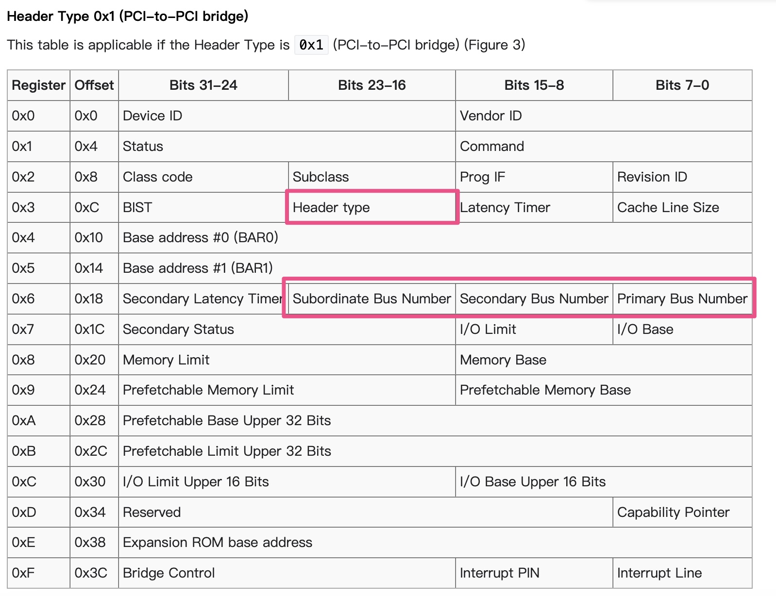
1 | /* Header type 1 (PCI-to-PCI bridges) */ |
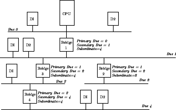
The problem is that at the time when you wish to configure any given PCI-PCI bridge you do not know the subordinate bus number for that bridge. You do not know if there are further PCI-PCI bridges downstream and if you did, you do not know what numbers will be assigned to them. The answer is to use a depthwise recursive algorithm and scan each bus for any PCI-PCI bridges assigning them numbers as they are found. As each PCI-PCI bridge is found and its secondary bus numbered, assign it a temporary subordinate number of 0xFF and scan and assign numbers to all PCI-PCI bridges downstream of it.
其实subordinate的计算是基于DFS算法的。
算法详细请参考Configuring PCI-PCI Bridges - Assigning PCI Bus Numbers
PCI-PCI bridges only pass a subset of PCI I/O and PCI memory read and write requests downstream. For example, in the following Figure, the PCI-PCI bridge will only pass read and write addresses from PCI bus 0 to PCI bus 1 if they are for PCI I/O or PCI memory addresses owned by either the SCSI or ethernet device; all other PCI I/O and memory addresses are ignored. This filtering stops addresses propogating needlessly throughout the system. To do this, the PCI-PCI bridges must be programmed with a base and limit for PCI I/O and PCI Memory space access that they have to pass from their primary bus onto their secondary bus.
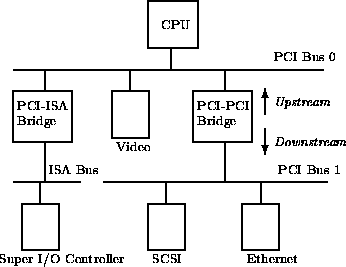
The PCI-PCI Bridge
We now cross the PCI-PCI Bridge and allocate PCI memory there:
The PCI-PCI Bridge’s PCI I/O and Memory Windows
We now return to the bridge and set its PCI I/O window at between 0x4000 and 0x40B0 and it’s PCI Memory window at between 0x400000 and 0x402000. This means that the PCI-PCI Bridge will ignore the PCI Memory accesses for the video device and pass them on if they are for the ethernet or scsi devices.
参考资料:
]]>
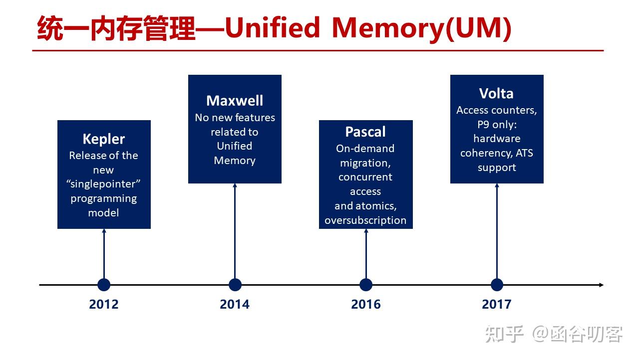
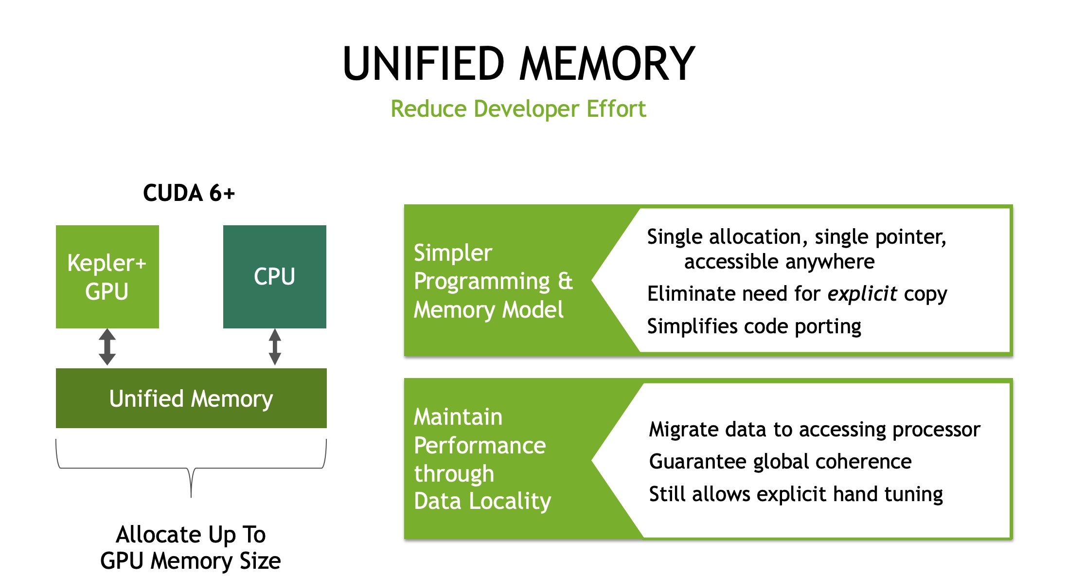
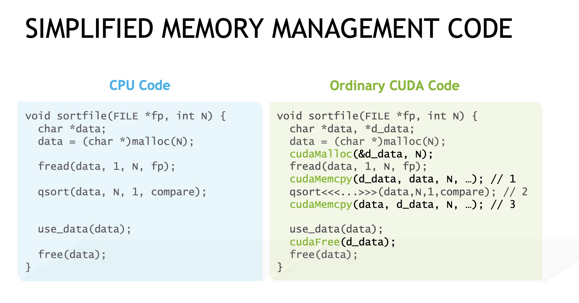
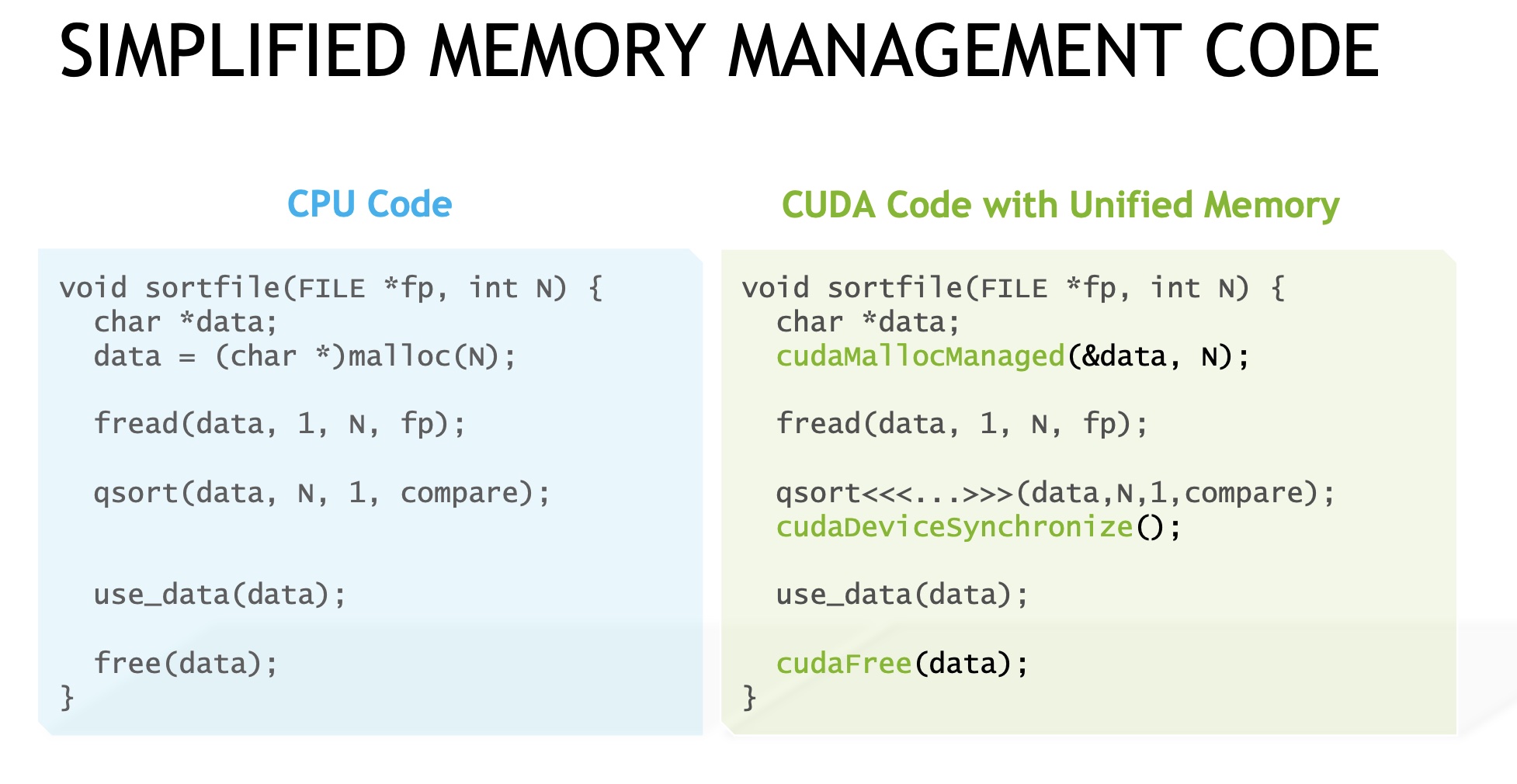
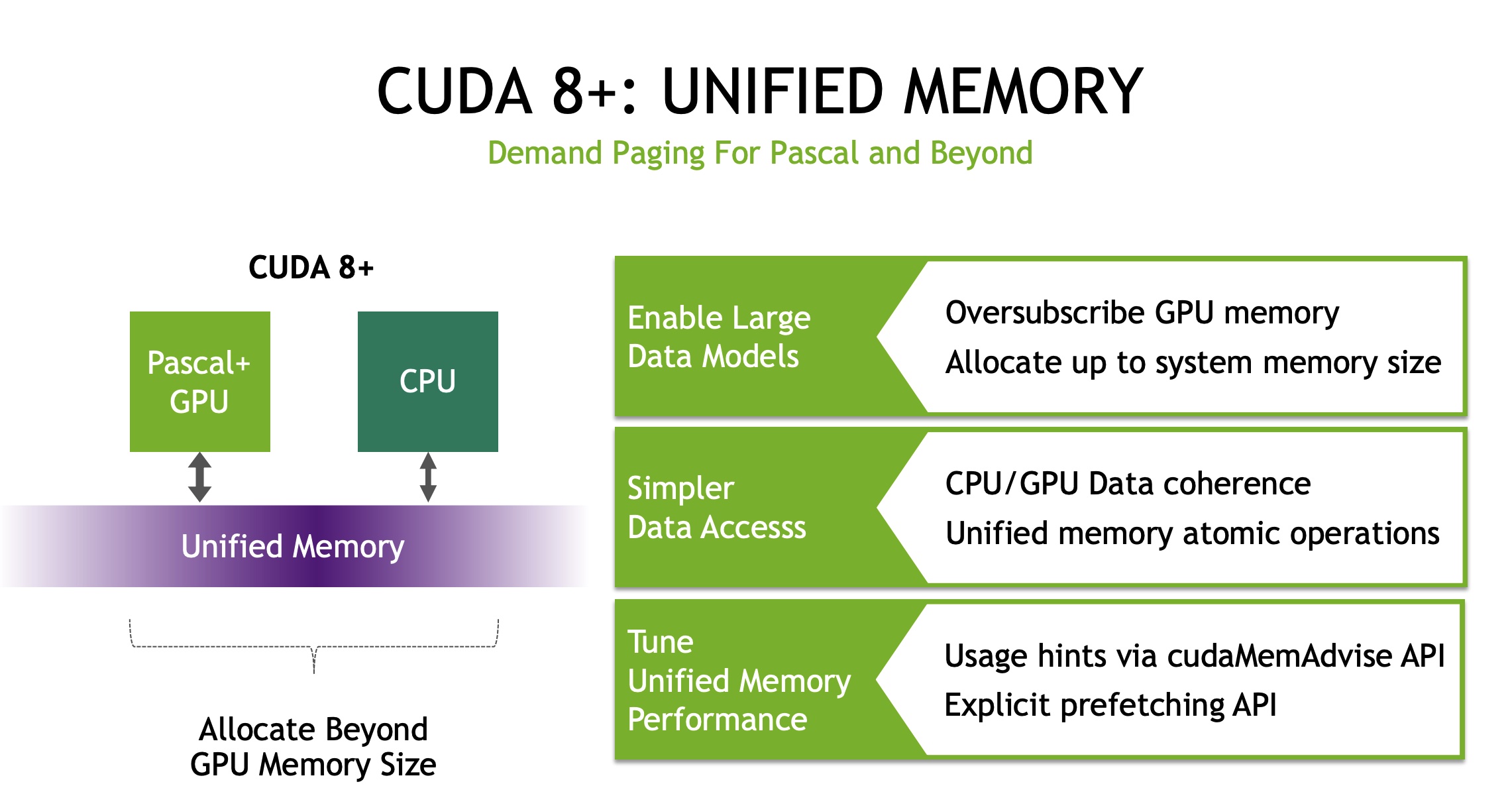
Traditionally, GPUs and CPUs have their own memory spaces, and applications running on one particular GPU cannot access the data directly from the memory of other GPUs or CPUs. To improve memory utilization, the latest NVIDIA PASCAL GPU released in 2016 supports unified memory , i.e., each GPU can access the whole memory space of both GPUs and CPUs via uniform memory addresses. In particular, the unified memory provides to all GPUs and CPUs a single memory address space, with an automatic page migration for data locality. The page migration engine also allows GPU threads to trigger page fault when the accessed data does not reside in GPU memory, and this makes the system eficiently migrate pages from anywhere in the system to the memory of GPUs in an on-demand manner.
The benefits of unified memory are twofold. First, it enables a GPU to handle dataset which is larger than its own memory size, because the unified memory can migrate data from CPU memory to GPU memory in an on-demand fashion. Second, using the unified memory can simplify the programming model. In particular, programmers can simply use a pointer to access data pages no matter where they reside, instead of explicitly calling data migration.
参考资料:
]]>为解决多进程对同一文件的读写冲突,在linux 系统中,提供了 flock 这一系统调用,用来实现对文件的读写保护,即文件锁的功能。文件锁保护文件的功能,与pthread 库中多线程使用读写锁来保护内存资源的方式是类似的。 flock 的 man page 中有如下介绍:
flock - apply or remove an advisory lock on an open file
从中可以解读出两点内容:
linux 中 flock 系统调用的原型如下:1
2
int flock(int fd, int operation);
当 flock 执行成功时,会返回0;当出现错误时,会返回 -1,并设置相应的 errno 值。
在flock 原型中,参数 operation 可以使用 LOCK_SH 或 LOCK_EX 常量,分别对应共享锁和排他锁。这两个常量的定义在 file.h 中。与 flock 相关的常量定义如下:
1 | /* Operations for the `flock' call. */ |
当使用 LOCK_SH 共享锁时,多个进程都可以使用共享锁锁定同一个文件,从而实现多个进程对文件的并行读取。由此可见,LOCK_SH 共享锁类似于多线程读写锁 pthread_rwlock_t 类型中的读锁。当使用LOCK_EX 排他锁时,同一时刻只能有一个进程锁定成功,其余进行只能阻塞,这种行为与多线程读写锁中的写锁类似。
flock 文件锁提供了阻塞和非阻塞两种使用方式。当处于阻塞模式时,如果当前进程无法成功获取到文件锁,那么进程就会一直阻塞等待,直到其他进程在对应文件上释放了锁,本进程能成功持有锁为止。在默认情况下,flock 提供是阻塞模式的文件锁。
在日常使用中,文件锁还会使用在另外一种场景下,即进程首先尝试对文件加锁,当加锁失败时,不希望进程阻塞,而是希望 flock 返回错误信息,进程进行错误处理后,继续进行下面的处理。在这种情形下就需要使用 flock 的非阻塞模式。把flock 的工作模式设置为非阻塞模式非常简单,只要将原有的 operation 参数改为锁的类型与 LOCK_NB 常量进行按位或操作即可,例如:
1 | int ret = flock(open_fd, LOCK_SH | LOCK_NB); |
在非阻塞模式下,加文件锁失败并不影响进程流程的执行,但要注意加入错误处理逻辑,在加锁失败时,不能对目标文件进行操作。
除了多种语言提供 flock 系统调用或函数,linux shell 中也提供了 flock 命令。
flock(1)
参考资料:
]]>1 | eventfd_signal |
1 | static int __wake_up_common(struct wait_queue_head *wq_head, unsigned int mode, |
由__wake_up_common的实现可知,最终eventfd_signal调用了wait_queue_entry的func回调。1
2
3
4
5
6
7
8
9/*
* A single wait-queue entry structure:
*/
struct wait_queue_entry {
unsigned intflags;
void*private;
wait_queue_func_tfunc;
struct list_headentry;
};
源码解析:vhost ioeventfd与irqfd中提到过vhost_poll_wakeup,那么这个函数又是如何与eventfd_signal关联起来的呢?
1 | void vhost_poll_init(struct vhost_poll *poll, vhost_work_fn_t fn, |
由上述代码片段可知,vhost_poll_wakeup被设置为了wait_queue_entry的func回调。
由此可知,eventfd_signal最终调用了vhost_poll_wakeup函数;因此,vhost_poll_wakeup函数运行上下文是vCPU线程(kvm调用了eventfd_signal,而kvm的运行上下文是vCPU线程)。
1 | ioeventfd_write |
wait_queue_entry的func回调1 | // for select and poll |
对于select和poll,wait_queue_entry的func回调是pollwake。
1 | // for epoll |
对于epoll,wait_queue_entry的func回调是ep_poll_callback。
为了方便起见,本文只详细介绍下pollwake。1
2
3
4
5
6
7
8
9
10
11
12
13
14
15
16
17
18
19
20
21
22
23
24
25
26
27
28
29
30
31
32
33// 在等待队列(wait_queue_t)上回调函数(func)
// 文件就绪后被调用,唤醒调用进程,其中key是文件提供的当前状态掩码
static int pollwake(wait_queue_t *wait, unsigned mode, int sync, void *key)
{
struct poll_table_entry *entry;
// 取得文件对应的poll_table_entry
entry = container_of(wait, struct poll_table_entry, wait);
// 过滤不关注的事件
if (key && !((unsigned long)key & entry->key)) {
return 0;
}
// 唤醒
return __pollwake(wait, mode, sync, key);
}
static int __pollwake(wait_queue_t *wait, unsigned mode, int sync, void *key)
{
struct poll_wqueues *pwq = wait->private;
// 将调用进程 pwq->polling_task 关联到 dummy_wait
DECLARE_WAITQUEUE(dummy_wait, pwq->polling_task);
smp_wmb();
pwq->triggered = 1;// 标记为已触发
// 唤醒调用进程
return default_wake_function(&dummy_wait, mode, sync, key);
}
// 默认的唤醒函数,poll/select 设置的回调函数会调用此函数唤醒
// 直接唤醒等待队列上的线程,即将线程移到运行队列(rq)
int default_wake_function(wait_queue_t *curr, unsigned mode, int wake_flags,
void *key)
{
// 这个函数比较复杂, 这里就不具体分析了
return try_to_wake_up(curr->private, mode, wake_flags);
}
参考资料:
]]>本文将详细的阐述virtio中的kick操作。根据kick操作的发展历史,按照如下顺序去介绍:
1 | /* the notify function used when creating a virt queue */ |
1 | // legacy device |
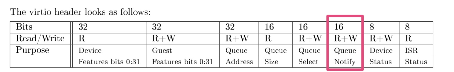
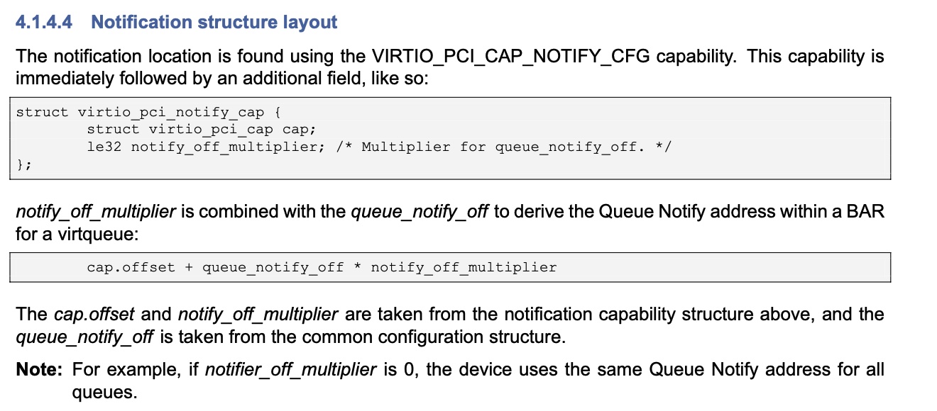
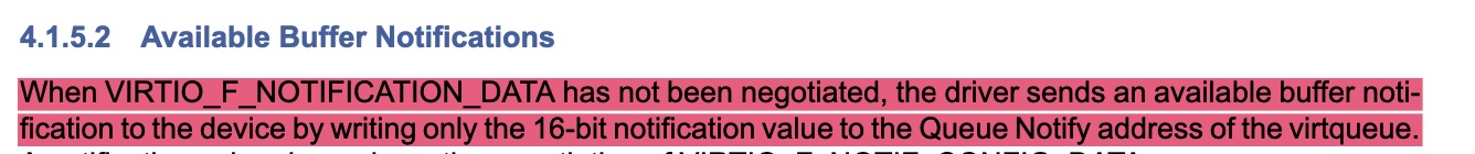
kick寄存器位于bar0中的VIRTIO_PCI_QUEUE_NOTIFY位置;不同vq使用同一个kick寄存器地址,往kick寄存器写入vq的index,告诉virtio后端要处理哪个vq。
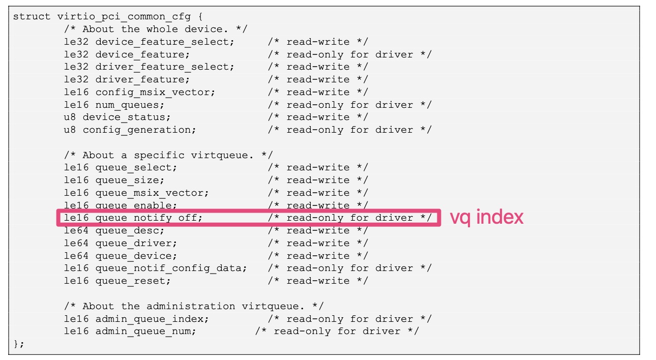
在设备实现中,一般会将queue_notify_off设置为vq index;也就是说,vp_modern_get_queue_notify_off的返回值,一般会与输入变量index相同。1
2
3
4
5
6
7
8
9
10
11
12
13
14/*
* vp_modern_get_queue_notify_off - get notification offset for a virtqueue
* @mdev: the modern virtio-pci device
* @index: the queue index
*
* Returns the notification offset for a virtqueue
*/
static u16 vp_modern_get_queue_notify_off(struct virtio_pci_modern_device *mdev,
u16 index)
{
vp_iowrite16(index, &mdev->common->queue_select);
return vp_ioread16(&mdev->common->queue_notify_off);
}
1 | // modern device |
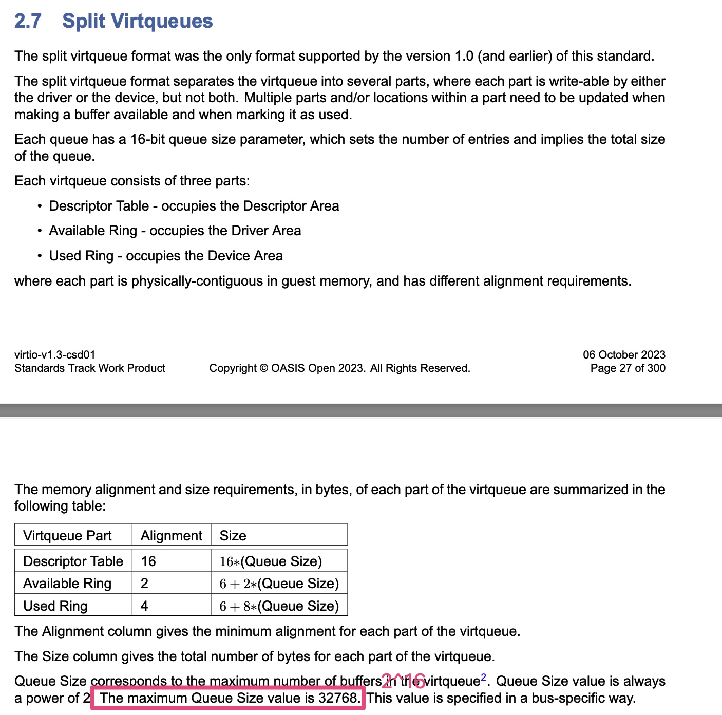
值得注意的是,对于split vq,desc table的最大size为2^16;对于packed vq,desc table的最大size为2^15;
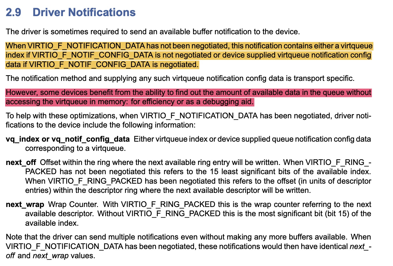
在kick寄存器中,不止存放了vq index:
vq_notif_config_data在一般情况下,就是vq index。
1 | // modern device |
1 | static bool vp_notify_with_data(struct virtqueue *vq) |
参考资料:
目前有若干种软件技术方案能实现GPU虚拟化,这些方案可以分为内核态虚拟化和用户态虚拟化两类。本文主要论述这两种方案的差异。
以英伟达的GPU为例,应用到硬件从上至下分为用户态、内核态、GPU硬件三个层次(见下图:CUDA软件栈)。
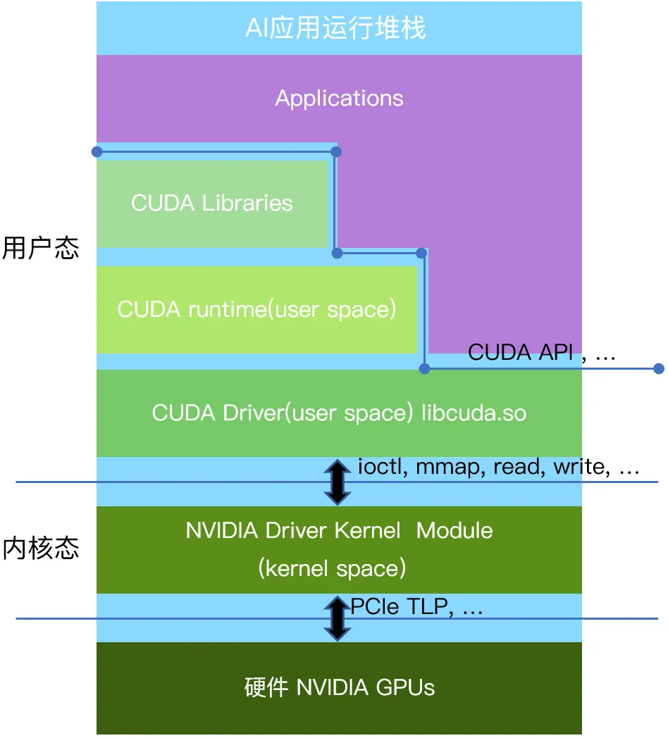
用户态是应用程序运行的环境。各种使用英伟达GPU的应用程序,比如人工智能计算类的应用,2D/3D图形渲染类的应用,都运行在用户态。为了便利编程以及安全因素,英伟达提供了用户态的运行库CUDA(Compute Unified Device Architecture)作为GPU并行计算的编程接口(类似的接口也包括由社区共同制订的OpenGL、Vulkan接口等),应用程序可以使用CUDA API来编写并行计算任务,并通过调用CUDA API与GPU用户态驱动进行通信。GPU用户态驱动再通过ioctl、mmap、read、write接口直接和GPU的内核态驱动进行交互。
该层主要运行的是GPU的内核态驱动程序,它与操作系统内核紧密集成,受到操作系统以及CPU硬件的特殊保护。内核态驱动可以执行特权指令,提供对硬件的访问和操作接口,并对GPU硬件进行底层控制。出于系统安全考虑,用户态的代码只能通过操作系统预先定义好的标准接口(Linux下有例如ioctl,mmap,read,write 等少量接口),调用内核态的代码。通过这些接口被调用的内核态代码一般是预先安装好的设备的内核态驱动。这样保证内核态和用户态的安全隔离,防止不安全的用户态代码破坏整个计算机系统。GPU的内核态驱动通过PCIe接口(也可能是其他硬件接口)以TLP报文的形式跟硬件进行通信。
特别的,包括英伟达在内的各类AI芯片产品的内核态和用户态之间的接口定义并不包含在例如CUDA、OpenGL、Vulkan等协议标准里面,他们也未曾向行业公开这一层的接口定义。因此各类行业应用也不会基于这一层的接口进行编程。
从技术可能性的角度来看,用户态与内核态各有相应的接口可以实现GPU虚拟化或者GPU池化:用户态的CUDA、OpenGL、Vulkan等应用运行时接口;内核态暴露的 ioctl、read、write等设备驱动接口。
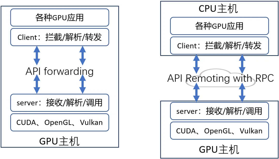
利用CUDA、OpenGL、Vulkan等标准接口,对API进行拦截和转发,对被拦截的函数进行解析,然后调用硬件厂商提供的用户态库中的相应函数(见上图)。拦截CUDA等用户态接口不需要在OS内核层进行设备文件的插入,因为这些接口的使用方式是操作系统在运行可执行文件的时候(例如Linux下的elf二进制),由操作系统的加载器自动在系统中按照固定的规则来寻找其依赖的外部接口,学术名称做符号(symbol)。那么根据操作系统寻找依赖的规则,很容易可以通过替换symbol的来源,使得当可执行文件发生例如CUDA接口调用的时候,调用的不是英伟达的闭源用户态软件提供的接口,而是一个经过修改后的同名接口,从而拦截到例如CUDA接口的调用。
经过API拦截之后,用户态虚拟化方案还可以利用RPC的方式进行远程API Remoting(见上图),即CPU主机可以通过网络调用GPU主机的GPU,实现GPU的远程调用。如此一来,多个GPU服务器可以组成资源池,供多个AI业务任意调用,达到实现GPU池化的目的。用户态虚拟化是一种软件的实现方案。目前业内已经成型的产品有:趋动科技的OrionX GPU池化产品,VMware的Bitfusion产品。这类技术方案拥有几个优点:
当然,这类方案也有缺点:相比于内核态接口,用户态API接口支持更复杂的参数和功能,因此用户态API接口的数量比内核态接口的数量要高几个数量级。这导致在用户态层实现GPU虚拟化和GPU池化的研发工作量要比在内核态实现要大得多。
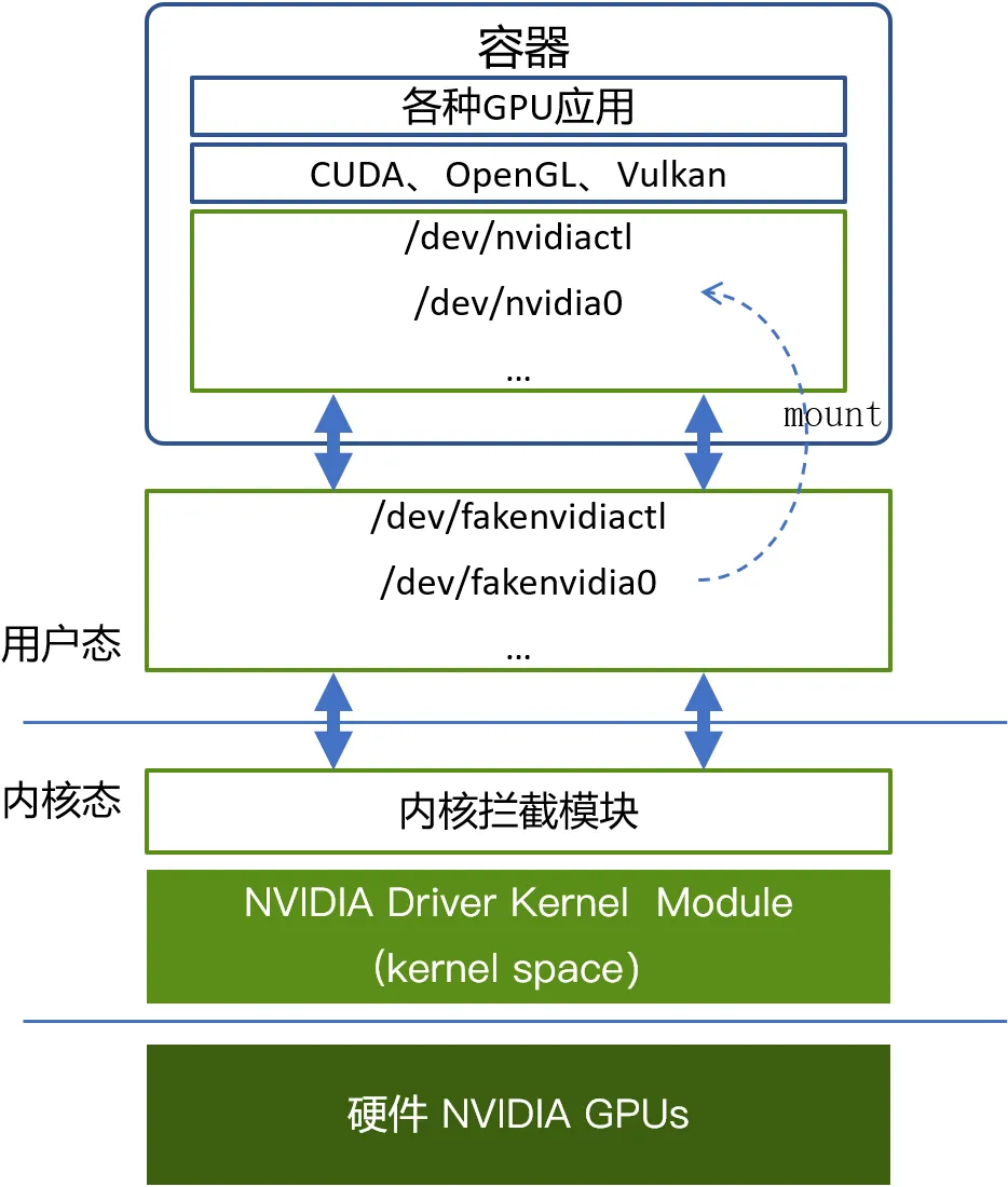
跟上述用户态拦截API类似的,第三方厂商所做的内核态虚拟化方案通过拦截ioctl、mmap、read、write等这类内核态与用户态之间的接口来实现GPU虚拟化。这类方案的关键点在于需要在操作系统内核里面增加一个内核拦截模块,并且在操作系统上创建一些设备文件来模拟正常的GPU设备文件。例如,英伟达GPU在Linux上的设备文件有/dev/nvidiactl、 /dev/nvidia0等多个文件。因此,在使用虚拟化的GPU时,把虚拟化出来的设备文件mount到业务容器内部,同时通过挂载重命名的机制伪装成英伟达的同名设备文件名,让应用程序访问。这样在容器内部的应用程序通过CUDA去访问设备文件的时候,仍然会去打开例如/dev/nvidiactl 和 /dev/nvidia0这样的设备文件,该访问就会被转发到模拟的设备文件,并向内核态发送例如ioctl这样的接口调用,进而被内核拦截模块截获并进行解析。目前国内的qGPU和cGPU方案都是工作在这一层。这类技术方案的优点是:
这类方案由于工作在内核态,缺点也是显而易见的:
上述两种虚拟化方案在经过接口拦截之后,就可以在当前的接口调用中被激活,接下来就是对该接口进行解析。不管是 ioctl 接口还是 CUDA接口,从计算机设计上,都可以表达为interface_name(paramerA, parameterB, …)这样的形式。也就是接口名称,接口参数(返回值也是一种参数形式)。而不管基于哪一层接口的拦截,这里的解析又分为两种:
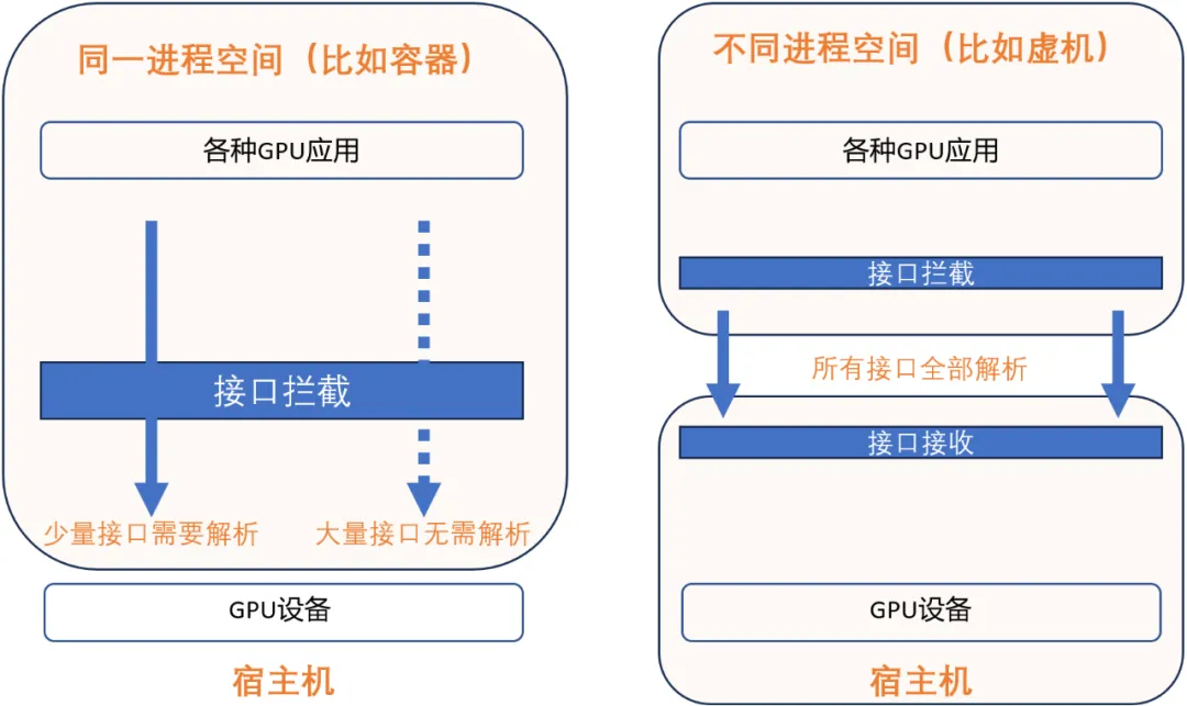
同一个进程空间的接口解析(见上图):在现代操作系统中,不管在用户态还是内核态,代码都执行在由CPU硬件 + 操作系统维护的一个进程空间里面,在一个进程空间里面有统一的进程上下文(context),并且所有的资源在进程空间内都是共享的,视图是统一的,包括访存地址空间(address space),也包括GPU设备上的资源。这个现代操作系统的设计可以为同一个进程空间的接口解析带来极大的便利。因为对于一个接口interface_name(paramerA, parameterB, …),即使存在不公开含义的参数,例如parameterB是不公开的,但是利用一个进程空间内所有的资源都是共享且视图统一的这个特点,只要确定该部分内容不需要被GPU虚拟化模拟执行所需要,那么虚拟化软件可以不需要对其进行解析,在截获之后,直接透传给英伟达自己的闭源模块就可以。实际上,只有少量接口,少量参数会被需要在一个进程内被解析并且模拟执行,因此选择这个技术路线可以“规避”掉绝大多数接口、参数的解析工作。具体以针对英伟达的GPU为例,只有非常少的接口、参数需要被真正解析并模拟执行。一些产品之所以能在非公开的内核接口层实现GPU虚拟化,是利用了同一个操作系统的特点,基于少量接口信息,来达到GPU虚拟化的目的。但是这样的技术路线也有一个非常明显的限制,就是只能在同一个进程空间内进行接口的拦截、解析和执行。因此这种技术路线从原理上就无法支持跨OS内核的KVM虚拟化,更无法跨越物理节点做到远程调用GPU。
不同进程空间的接口解析(见上图):当GPU应用所在的操作系统和管理物理GPU所在的操作系统是两个不同的操作系统的时候,要达到GPU虚拟化、GPU池化的目的,就需要跨进程对选定的GPU接口层进行跨进程的接口解析。典型的场景如 KVM虚拟机,还有跨物理节点调用GPU。由于应用程序和GPU管理软件栈(例如GPU驱动)已经不在一个操作系统的管理下,因此资源就不再是共享的了,视图也不再是统一的了。例如,同样的一个虚拟地址(virtual address)在不同的进程空间代表的很可能是不一样的内容。所以对于所有接口interface_name(paramerA, parameterB, …),都要进行完善的解析、处理,并通过例如网络的方式跨越操作系统进行传送。以英伟达的 CUDA 为例有数万个接口,需要对每一个接口都进行跨进程空间的接口解析,然后进行行为模拟。因此,在不公开的接口层进行跨进程空间的接口解析,原理上是行不通的。
经过接口解析之后,则需要向GPU应用提供一个模拟的GPU执行环境,这个模拟的动作是由GPU虚拟化和GPU池化的软件来完成的。不同软件提供的模拟的能力是有差异的,但是其基础的能力,都是要保持对上层应用的透明性,使得应用不需要改动实现,不需要重新编译。
对于GPU虚拟化和资源池化,由于在接口层的的选择上有两个分支,在接口解析上也有两个分支,所以排列组合起来有4种可能,下面对4种方式做一个对比。
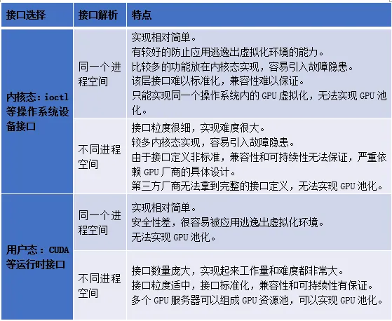
通过对比这4种可能的方式,我们做个总结: