深入理解DMA part1
本文将介绍DMA的基础概念和use interface from system programmer’s perspective。
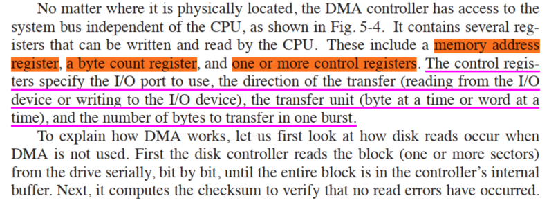
1. Background
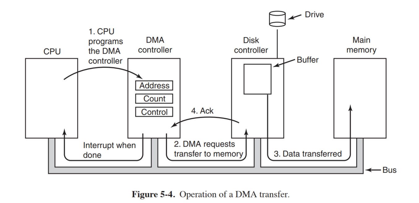
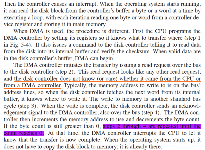
2. Overview
Let’s review how a DMA transfer takes place, considering only input transfers to simplify the discussion.
Data transfer can be triggered in two ways: either the software asks for data (via a function such as read) or the hardware asynchronously pushes data to the system.
In the first case, the steps involved can be summarized as follows:
- When a process calls read, the driver method allocates a DMA buffer and instructs the hardware to transfer its data into that buffer. The process is put to sleep.
- The hardware writes data to the DMA buffer and raises an interrupt when it’s done.
- The interrupt handler gets the input data, acknowledges the interrupt, and awakens the process, which is now able to read data.
The second case comes about when DMA is used asynchronously. This happens, for example, with data acquisition devices that go on pushing data even if nobody is reading them. In this case, the driver should maintain a buffer so that a subsequent read call will return all the accumulated data to user space. The steps involved in this kind of transfer are slightly different:
- The hardware raises an interrupt to announce that new data has arrived.
- The interrupt handler allocates a buffer and tells the hardware where to transfer its data.
- The peripheral device writes the data to the buffer and raises another interrupt when it’s done.
- The handler dispatches the new data, wakes any relevant process, and takes care of housekeeping.
3. A simple PCI DMA example
As an example of how the DMA mappings might be used, we present a simple example of DMA coding for a PCI device. The actual form of DMA operations on the PCI bus is very dependent on the device being driven. Thus, this example does not apply to any real device; instead, it is part of a hypothetical driver called dad (DMA Acquisition Device). A driver for this device might define a transfer function like this:1
2
3
4
5
6
7
8
9
10
11
12
13
14
15
16
17
18
19int dad_transfer(struct dad_dev *dev, int write, void *buffer,
size_t count)
{
dma_addr_t bus_addr;
/* Map the buffer for DMA */
dev->dma_dir = (write ? DMA_TO_DEVICE : DMA_FROM_DEVICE);
dev->dma_size = count;
bus_addr = dma_map_single(&dev->pci_dev->dev, buffer, count,
dev->dma_dir);
dev->dma_addr = bus_addr;
/* Set up the device */
writeb(dev->registers.command, DAD_CMD_DISABLEDMA);
writeb(dev->registers.command, write ? DAD_CMD_WR : DAD_CMD_RD);
writel(dev->registers.addr, cpu_to_le32(bus_addr));
writel(dev->registers.len, cpu_to_le32(count));
/* Start the operation */
writeb(dev->registers.command, DAD_CMD_ENABLEDMA);
return 0;
}
This function maps the buffer to be transferred and starts the device operation. The other half of the job must be done in the interrupt service routine, which looks something like this:1
2
3
4
5
6
7
8
9
10void dad_interrupt(int irq, void *dev_id, struct pt_regs *regs)
{
struct dad_dev *dev = (struct dad_dev *) dev_id;
/* Make sure it's really our device interrupting */
/* Unmap the DMA buffer */
dma_unmap_single(dev->pci_dev->dev, dev->dma_addr,
dev->dma_size, dev->dma_dir);
/* Only now it is safe to access the buffer, copy to user, etc. */
...
}
3.1 more detailed explanation
The steps involved to transfer the data to the device could be summarized as follows :
- Assume that you have the data in a buffer.
- The driver creates a DMA mapping for this buffer (say using
pci_alloc_consistent()or the newerdma_alloc_coherent()), and returns the corresponding DMA bus address(physical address). - This DMA bus address is to be informed to the device. This is done by writing into the correct DMA registers of the device through
writel()(assuming that the device registers are memory mapped). - The device also needs to be informed about the amount of data that is being transferred and such (by writing to the appropriate registers of the device using
writel()) - Now issue the command to the device to start the DMA transactions by writing to one of its control registers (again possibly using
writel()). - Once the data transaction is completed, the device issues an interrupt.
- In the interrupt handler, the driver may unallocate the buffer which was used for transaction and might as well perform DMA unmapping.
And there you have it. The data is transferred to the device!
参考资料:
- How does a DMA controller work?
- DMA and I/O memory region under Linux
- Linux Device Drivers, Third Edition
- MODERN OPERATING SYSTEMS, FOURTH EDITION by ANDREW S. TANENBAUM