Notes about qemu pxb(pci expander bridge)
本文将mark下qemu pxb(pci expander bridge)的相关notes。
Introduction
PXB is a “light-weight” host bridge whose purpose is to enable the main host bridge to support multiple PCI root buses.
As oposed to PCI-2-PCI bridge’s secondary bus, PXB’s bus is a primary bus and can be associated with a NUMA node(different from the main host bridge) allowing the guest OS to recognize the proximity of a pass-through device to other resources as RAM and CPUs.
The PXB is composed from:
- A primary PCI bus (can be associated with a NUMA node)
Acts like a normal pci bus and from the functionality point
of view is an “expansion” of the bus behind the
main host bridge. - A pci-2-pci bridge behind the primary PCI bus where the actual
devices will be attached. - A host-bridge PCI device
Situated on the bus behind the main host bridge, allows
the BIOS to configure the bus number and IO/mem resources.
It does not have its own config/data register for configuration
cycles, this being handled by the main host bridge.
- A host-bridge sysbus to comply with QEMU current design.
PCI Root Bus
This section demonstrates how to create extra PCI root buses through the “light-weight” PXB (PCI Expander Bridge) host bridge. It is “pxb” in QEMU command line. It is implemented only for i440fx and can be placed only on bus 0.1
2
3
4
5
6
7
8qemu-system-x86_64 -machine pc,accel=kvm -vnc :8 -smp 4 -m 4096M \
-net nic -net user,hostfwd=tcp::5028-:22 \
-hda ol8.qcow2 -serial stdio \
-device pxb,id=bridge1,bus=pci.0,bus_nr=3 \
-device virtio-scsi-pci,bus=bridge1,addr=0x3 \
-device pxb,id=bridge2,bus=pci.0,bus_nr=8 \
-device virtio-scsi-pci,bus=bridge2,addr=0x3 \
-device virtio-scsi-pci,bus=bridge2,addr=0x4
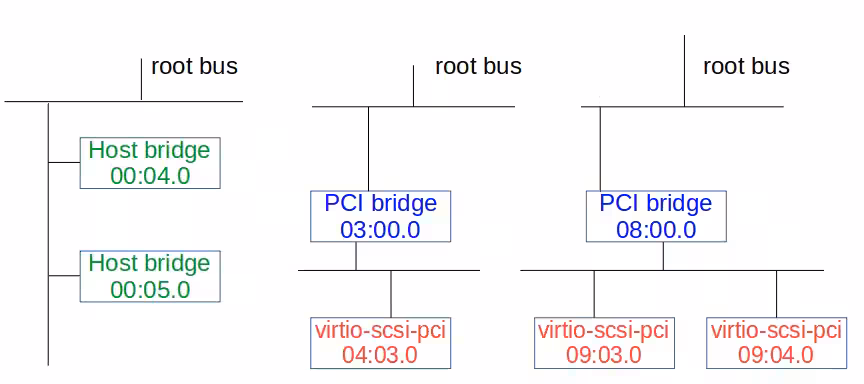
The above QEMU command line creates two extra PCI root buses. The first root bus (04:00.0) has one virtio-scsi-pci HBA (04:03.0), and the second root bus (09:00.0) has two virtio-scsi-pci HBAs (09:03.0 and 09:04.0).1
2
3
4
5
6
7
8
9
10
11
12
13
14[root@vm ~]# lspci
00:00.0 Host bridge: Intel Corporation 440FX - 82441FX PMC [Natoma] (rev 02)
00:01.0 ISA bridge: Intel Corporation 82371SB PIIX3 ISA [Natoma/Triton II]
00:01.1 IDE interface: Intel Corporation 82371SB PIIX3 IDE [Natoma/Triton II]
00:01.3 Bridge: Intel Corporation 82371AB/EB/MB PIIX4 ACPI (rev 03)
00:02.0 VGA compatible controller: Device 1234:1111 (rev 02)
00:03.0 Ethernet controller: Intel Corporation 82540EM Gigabit Ethernet Controller (rev 03)
00:04.0 Host bridge: Red Hat, Inc. QEMU PCI Expander bridge
00:05.0 Host bridge: Red Hat, Inc. QEMU PCI Expander bridge
03:00.0 PCI bridge: Red Hat, Inc. QEMU PCI-PCI bridge
04:03.0 SCSI storage controller: Red Hat, Inc. Virtio SCSI
08:00.0 PCI bridge: Red Hat, Inc. QEMU PCI-PCI bridge
09:03.0 SCSI storage controller: Red Hat, Inc. Virtio SCSI
09:04.0 SCSI storage controller: Red Hat, Inc. Virtio SCSI
The below lspci output and figure depict the PCI bus topology for this example.
1 | [root@vm ~]# lspci -t |
PCIe Root Complex
This section demonstrates how to create extra PCIe root buses through extra Root Complexes. According to QEMU source code, PCIe features are supported only by ‘q35’ machine type on x86 architecture and the ‘virt’ machine type on AArch64. The root complex is created by using “pxb-pcie” on the QEMU command line.1
2
3
4
5
6
7
8
9
10
11qemu-system-x86_64 -machine q35,accel=kvm -vnc :8 -smp 4 -m 4096M \
-net nic -net user,hostfwd=tcp::5028-:22 \
-hda ol8.qcow2 -serial stdio \
-device pxb-pcie,id=pcie.1,bus_nr=2,bus=pcie.0 \
-device ioh3420,id=pcie_port1,bus=pcie.1,chassis=1 \
-device virtio-scsi-pci,bus=pcie_port1 \
-device ioh3420,id=pcie_port2,bus=pcie.1,chassis=2 \
-device virtio-scsi-pci,bus=pcie_port2 \
-device pxb-pcie,id=pcie.2,bus_nr=8,bus=pcie.0 \
-device ioh3420,id=pcie_port3,bus=pcie.2,chassis=3 \
-device virtio-scsi-pci,bus=pcie_port3
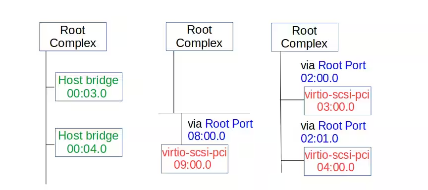
The above QEMU command line creates two extra PCIe root complexes. The first root complex has one virtio-scsi-pci HBA (09:00.0), and the second has two virtio-scsi-pci HBAs (03:00.0 and 04:00.0).1
2
3
4
5
6
7
8
9
10
11
12
13
14
15[root@vm ~]# lspci
00:00.0 Host bridge: Intel Corporation 82G33/G31/P35/P31 Express DRAM Controller
00:01.0 VGA compatible controller: Device 1234:1111 (rev 02)
00:02.0 Ethernet controller: Intel Corporation 82574L Gigabit Network Connection
00:03.0 Host bridge: Red Hat, Inc. QEMU PCIe Expander bridge
00:04.0 Host bridge: Red Hat, Inc. QEMU PCIe Expander bridge
00:1f.0 ISA bridge: Intel Corporation 82801IB (ICH9) LPC Interface Controller (rev 02)
00:1f.2 SATA controller: Intel Corporation 82801IR/IO/IH (ICH9R/DO/DH) 6 port SATA Controller [AHCI mode] (rev 02)
00:1f.3 SMBus: Intel Corporation 82801I (ICH9 Family) SMBus Controller (rev 02)
02:00.0 PCI bridge: Intel Corporation 7500/5520/5500/X58 I/O Hub PCI Express Root Port 0 (rev 02)
02:01.0 PCI bridge: Intel Corporation 7500/5520/5500/X58 I/O Hub PCI Express Root Port 0 (rev 02)
03:00.0 SCSI storage controller: Red Hat, Inc. Virtio SCSI (rev 01)
04:00.0 SCSI storage controller: Red Hat, Inc. Virtio SCSI (rev 01)
08:00.0 PCI bridge: Intel Corporation 7500/5520/5500/X58 I/O Hub PCI Express Root Port 0 (rev 02)
09:00.0 SCSI storage controller: Red Hat, Inc. Virtio SCSI (rev 01)
The below lspci output and figure depict the PCIe topology for this example.1
2
3
4
5
6
7
8
9
10
11
12[root@vm ~]# lspci -t
-+-[0000:08]---00.0-[09]----00.0
+-[0000:02]-+-00.0-[03]----00.0
| \-01.0-[04]----00.0
\-[0000:00]-+-00.0
+-01.0
+-02.0
+-03.0
+-04.0
+-1f.0
+-1f.2
\-1f.3
参考资料: